Infiniti G20 (P11). Manual - part 346


  Index      Infiniti     Infiniti G20 (P11) - service repair manual 1999-2002 year


Search            


Content   ..  344  345  346  347   ..


Infiniti G20 (P11). Manual - part 346


2

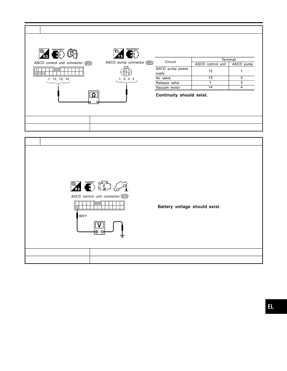
CHECK ASCD PUMP CIRCUIT

1. Disconnect ASCD control unit harness connector.
2. Check harness for open or short between ASCD control unit and ASCD pump.

SEL269WA

OK or NG

OK

©

GO TO 3.

NG

©

Repair harness.

3

CHECK ASCD PUMP POWER SUPPLY

1. Jack-up the drive wheels.
2. Maintain the conditions below.

I

Vehicle speed is more than 40 km/h (25 MPH).

I

Main switch (CRUISE lamp) is ON.

I

Set/coast switch (SET lamp) is ON.

Check voltage between ASCD control unit harness connector terminal 12 and ground.

SEL381WA

OK or NG

OK

©

ASCD pump power supply is OK.

NG

©

Replace ASCD control unit.

GI

MA

EM

LC

EC

FE

CL

MT

AT

AX

SU

BR

ST

RS

BT

HA

SC

IDX

AUTOMATIC SPEED CONTROL DEVICE (ASCD)

Trouble Diagnoses (Cont’d)

EL-161

ASCD ACTUATOR/PUMP CHECK

=NCEL0099S10

1

CHECK VACUUM HOSE

Check vacuum hose (between ASCD actuator and ASCD pump) for breakage, cracks or fracture.

MEL402G

OK or NG

OK

©

GO TO 2.

NG

©

Repair or replace hose.

2

CHECK ASCD WIRE

Check wire for improper installation, rust formation or breaks.

OK or NG

OK

©

GO TO 3.

NG

©

Repair or replace wire. Refer to “ASCD Wire Adjustment” (EL-165).

3

CHECK ASCD ACTUATOR

1. Disconnect vacuum hose from ASCD actuator.
2. Connect the hose of hand vacuum pump to ASCD actuator.

SEL264W

OK or NG

OK

©

GO TO 4.

NG

©

Replace ASCD actuator.

AUTOMATIC SPEED CONTROL DEVICE (ASCD)

Trouble Diagnoses (Cont’d)

EL-162

4

CHECK ASCD PUMP

1. Disconnect vacuum hose from ASCD pump and ASCD pump connector.
2. If necessary remove ASCD pump.
3. Connect vacuum gauge to ASCD pump.
4. Apply 12V direct current to ASCD pump and check operation.

SEL265W

OK or NG

OK

©

INSPECTION END

NG

©

Replace ASCD pump.

THROTTLE POSITION SENSOR SIGNAL CHECK

NCEL0099S11

1

CHECK THROTTLE POSITION SENSOR SIGNAL CIRCUIT

1. Disconnect ECM harness connector and ASCD control unit harness connector.
2. Check continuity between ECM terminal 71 and ASCD control unit terminal 3.

SEL268WA

OK or NG

OK

©

Refer to “TROUBLE DIAGNOSIS FOR INTERMITTENT INCIDENT” in EC section. (EC-
146)

NG

©

Repair harness.

GI

MA

EM

LC

EC

FE

CL

MT

AT

AX

SU

BR

ST

RS

BT

HA

SC

IDX

AUTOMATIC SPEED CONTROL DEVICE (ASCD)

Trouble Diagnoses (Cont’d)

EL-163

CEL981-A

Electrical Component Inspection

=NCEL0100

ASCD BRAKE SWITCH AND STOP LAMP SWITCH

NCEL0100S02

Condition

Continuity

ASCD brake

switch

Stop lamp switch

When brake pedal is depressed

No

Yes

When brake pedal is released

Yes

No

Check each switch after adjusting brake pedal — refer to BR-12,
“BRAKE PEDAL AND BRACKET”.

SEL707PG

ASCD CLUTCH SWITCH (FOR M/T MODELS)

NCEL0100S04

Condition

Continuity

When clutch pedal is depressed

No

When clutch pedal is released

Yes

CEL982

PARK/NEUTRAL POSITION SWITCH (FOR A/T
MODELS)

NCEL0100S03

A/T selector lever position

Continuity

Between terminals 1 and 2

“P”

Yes

“N”

Yes

Except “P” and “N”

No

AUTOMATIC SPEED CONTROL DEVICE (ASCD)

Electrical Component Inspection

EL-164


Content   ..  344  345  346  347   ..