Infiniti G20 (P11). Manual - part 332
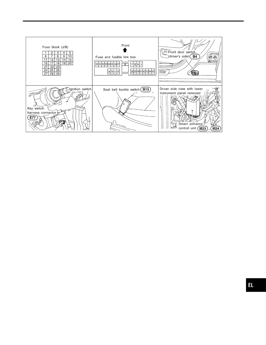
Component Parts and Harness Connector
Location
NCEL0052
SEL834VA
System Description
NCEL0053
The warning chime is controlled by the smart entrance control unit.
The warning chime is located in the smart entrance control unit.
Power is supplied at all times
I
through 10A fuse [No. 24, located in the fuse block (J/B)]
I
to key switch terminal 1.
Power is supplied at all times
I
through 10A fuse [No. 34, located in the fuse block (J/B)]
I
to tail lamp relay terminals 1 and 3.
Power is supplied at all times
I
through 30A fusible link (letter d, located in the fuse and fusible link box).
I
to smart entrance control unit terminal 11.
With the ignition switch in the ON or START position, power is supplied
I
through 10A fuse [No. 8, located in the fuse block (J/B)]
I
to smart entrance control unit terminal 33.
Ground is supplied to smart entrance control unit terminal 16 through body grounds M15, M71 and M76.
IGNITION KEY WARNING CHIME
NCEL0053S01
With the key in the ignition switch in the OFF or ACC position, and the driver’s door open, the warning chime
will sound. A battery positive voltage is supplied
I
from key switch terminal 1
I
to smart entrance control unit terminal 32.
Ground is supplied
I
from front door switch LH terminal 2
I
to smart entrance control unit terminal 29.
Front door switch LH terminal 3 is grounded through body grounds B7 and B24.
LIGHT WARNING CHIME
NCEL0053S02
With ignition switch OFF or ACC, driver’s door open, warning chime will sound. [Except when headlamp bat-
tery saver control operates (for 45 seconds after ignition switch is turned to OFF or ACC position) and head-
lamps do not illuminate.] A battery positive voltage is supplied.
I
from tail lamp relay terminal 5
GI
MA
EM
LC
EC
FE
CL
MT
AT
AX
SU
BR
ST
RS
BT
HA
SC
IDX
WARNING CHIME
Component Parts and Harness Connector Location
EL-105