Infiniti G20 (P11). Manual - part 313
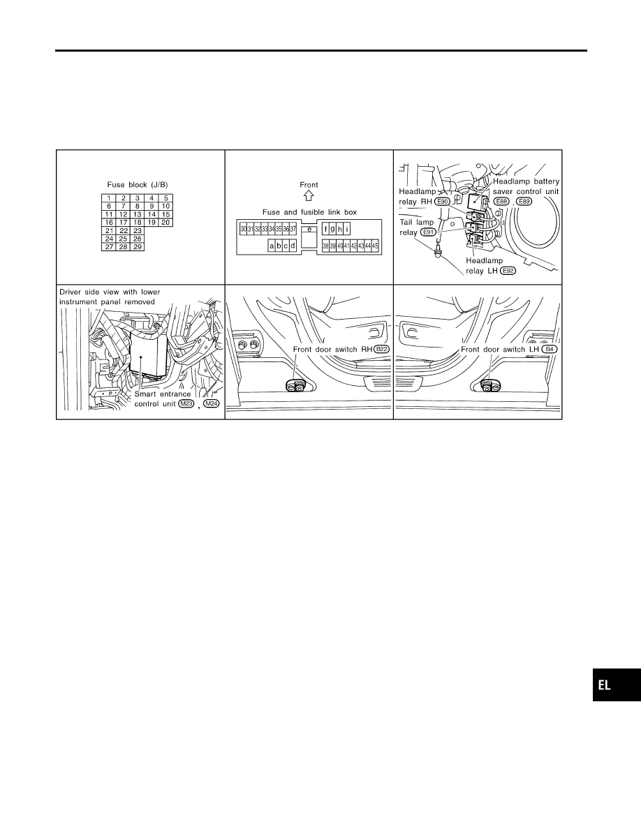
Component Parts and Harness Connector
Location
NCEL0164
SEL665W
System Description
NCEL0012
The headlamp operation is controlled by the lighting switch which is built into the combination switch and
headlamp battery saver control unit. And the headlamp battery saver system is controlled by the headlamp
battery saver control unit and smart entrance control unit.
OUTLINE
NCEL0012S04
Power is supplied at all times
I
to headlamp LH relay terminals 1 and 3
I
through 15A fuse (No. 32, located in the fuse and fusible link box), and
I
to headlamp RH relay terminals 1 and 3
I
through 15A fuse (No. 33, located in the fuse and fusible link box), and
I
to headlamp battery saver control unit terminal 7
I
through 10A fuse [No. 24, located in the fuse block (J/B)].
When the ignition switch is in the ON or START position, power is supplied
I
to headlamp battery saver control unit terminal 1
I
through 10A fuse [No. 16, located in the fuse block (J/B)], and
I
to headlamp battery saver control unit terminal 10, and
I
to smart entrance control unit terminal 33
I
through 10A fuse [No. 8, located in the fuse block (J/B)]
Ground is supplied to headlamp battery saver control unit terminals 4 and 11.
GI
MA
EM
LC
EC
FE
CL
MT
AT
AX
SU
BR
ST
RS
BT
HA
SC
IDX
HEADLAMP (FOR USA)
Component Parts and Harness Connector Location
EL-29