Infiniti G20 (P11). Manual - part 295
Wiring Diagram
NCEC0324
TEC833
GI
MA
EM
LC
FE
CL
MT
AT
AX
SU
BR
ST
RS
BT
HA
SC
EL
IDX
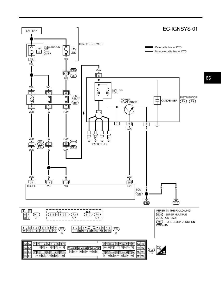
IGNITION SIGNAL
Wiring Diagram
EC-591
|
|
|
Wiring Diagram NCEC0324 TEC833 GI MA EM LC FE CL MT AT AX SU BR ST RS BT HA SC EL IDX IGNITION SIGNAL Wiring Diagram EC-591 |