Infiniti G20 (P11). Manual - part 273
5
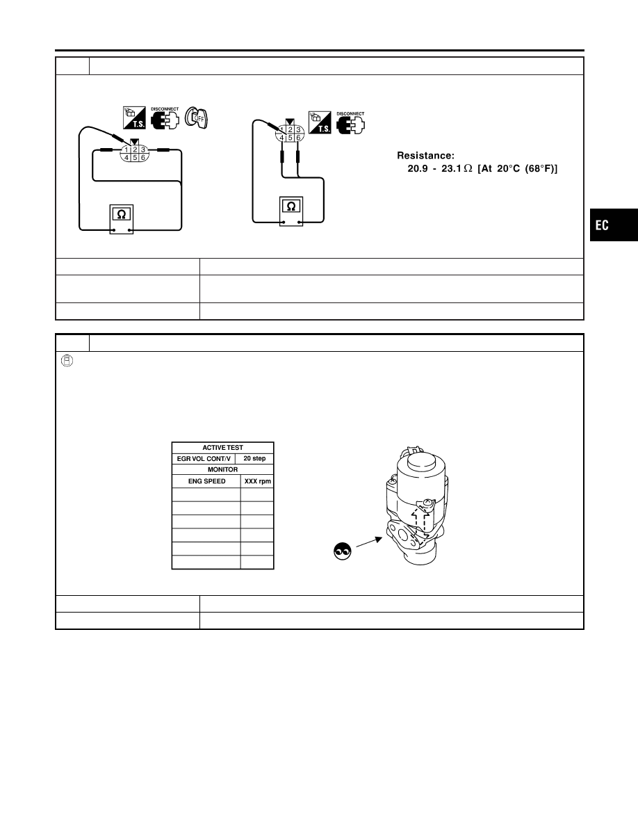
CHECK EGR VOLUME CONTROL VALVE-I
1. Disconnect EGR volume control valve.
2. Check resistance between EGR volume control valve terminal 2 and terminals 1, 3, terminal 5 and terminals 4, 6.
SEF588X
OK or NG
OK (With CONSULT-II)
©
GO TO 6.
OK (Without CONSULT-
II)
©
GO TO 7.
NG
©
Replace EGR volume control valve.
6
CHECK EGR VOLUME CONTROL VALVE-II
With CONSULT-II
1. Remove EGR volume control valve.
2. Reconnect ECM harness connector and EGR volume control valve harness connector.
3. Turn ignition switch ON.
4. Perform “EGR VOL CONT/V” in “ACTIVE TEST” mode with CONSULT-II.
5. Check that EGR volume control valve shaft moves smoothly forward and backward according to the valve opening
steps.
SEF067Y
OK or NG
OK
©
GO TO 8.
NG
©
Replace EGR volume control valve.
GI
MA
EM
LC
FE
CL
MT
AT
AX
SU
BR
ST
RS
BT
HA
SC
EL
IDX
DTC P1401 EGR TEMPERATURE SENSOR
Diagnostic Procedure (Cont’d)
EC-503