Infiniti G20 (P11). Manual - part 229


  Index      Infiniti     Infiniti G20 (P11) - service repair manual 1999-2002 year


Search            


Content   ..  227  228  229  230   ..


Infiniti G20 (P11). Manual - part 229


12

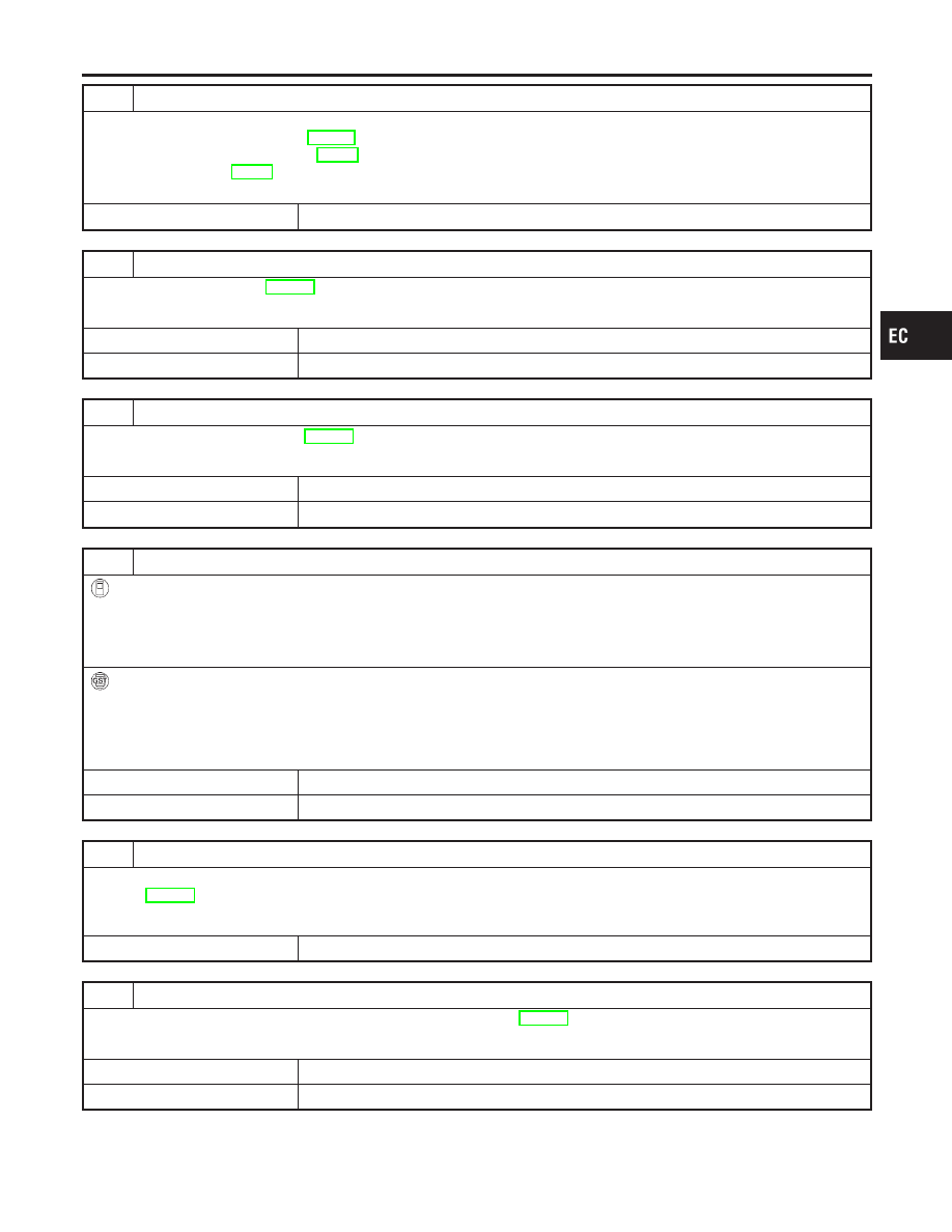
DETECT MALFUNCTIONING PART

Check the following.

I

Fuel pump and circuit (Refer to EC-605.)

I

Fuel pressure regulator (Refer to EC-51.)

I

Fuel lines. Refer to MA-16, “Checking Fuel Lines”.

I

Fuel filter for clogging

©

Repair or replace.

13

CHECK IGNITION TIMING

Perform “Basic Inspection”, EC-107.

OK or NG

OK

©

GO TO 14.

NG

©

Adjust ignition timing.

14

CHECK HEATED OXYGEN SENSOR 1 (FRONT)

Refer to “Component Inspection”, EC-202.

OK or NG

OK

©

GO TO 15.

NG

©

Replace heated oxygen sensor 1 (front).

15

CHECK MASS AIR FLOW SENSOR

With CONSULT-II

Check “MASS AIR FLOW” in “DATA MONITOR” mode with CONSULT-II.

at idling: 2.5 - 5.0 g·m/sec
at 2,500 rpm: 7.1 - 12.5 g·m/sec

With GST

Check mass air flow sensor signal in MODE 1 with GST.

at idling: 2.5 - 5.0 g·m/sec
at 2,500 rpm: 7.1 - 12.5 g·m/sec

OK or NG

OK

©

GO TO 17.

NG

©

GO TO 16.

16

CHECK CONNECTORS

Check connectors for rusted terminals or loose connections in the mass air flow sensor circuit or engine grounds.
Refer to EC-154.

OK or NG

NG

©

Repair or replace it.

17

CHECK SYMPTOM MATRIX CHART

Check items on the rough idle symptom in “Symptom Matrix Chart”, EC-125.

OK or NG

OK

©

GO TO 18.

NG

©

Repair or replace.

GI

MA

EM

LC

FE

CL

MT

AT

AX

SU

BR

ST

RS

BT

HA

SC

EL

IDX

DTC P0300 - P0304 NO. 4 - 1 CYLINDER MISFIRE, MULTIPLE CYLINDER

MISFIRE

Diagnostic Procedure (Cont’d)

EC-327

18

ERASE THE 1ST TRIP DTC

Some tests may cause a 1st trip DTC to be set.
Erase the 1st trip DTC from the ECM memory after performing the tests. Refer to EC-79.

©

GO TO 19.

19

CHECK INTERMITTENT INCIDENT

Perform “TROUBLE DIAGNOSIS FOR INTERMITTENT INCIDENT”, EC-146.

©

INSPECTION END

SEF174P

Component Inspection

NCEC0205

IGNITION WIRES

NCEC0205S01

1.

Inspect wires for cracks, damage, burned terminals and for
improper fit.

2.

Measure the resistance of wires to their distributor cap termi-
nal. Move each wire while testing to check for intermittent
breaks.

Resistance:

13.6 - 18.4 k

/m (4.15 - 5.61 k

/ft) at 25°C (77°F)

If the resistance exceeds the above specification, inspect igni-
tion wire to distributor cap connection. Clean connection or
replace the ignition wire with a new one.

DTC P0300 - P0304 NO. 4 - 1 CYLINDER MISFIRE, MULTIPLE CYLINDER

MISFIRE

Diagnostic Procedure (Cont’d)

EC-328

SEF598K

Component Description

NCEC0206

The knock sensor is attached to the cylinder block. It senses
engine knocking using a piezoelectric element. A knocking vibration
from the cylinder block is sensed as vibrational pressure. This
pressure is converted into a voltage signal and sent to the ECM.
Freeze frame data will not be stored in the ECM for the knock
sensor. The MIL will not light for knock sensor malfunction.
The knock sensor has one trip detection logic.

ECM Terminals and Reference Value

NCEC0207

Specification data are reference values and are measured between each terminal and ground.

CAUTION:

Do not use ECM ground terminals when measuring input/output voltage. Doing so may result in dam-
age to the ECM’s transistor. Use a ground other than ECM terminals, such as the ground.

TERMI-

NAL

NO.

WIRE

COLOR

ITEM

CONDITION

DATA (DC Voltage)

81

W

Knock sensor

[Engine is running]

I

Idle speed

Approximately 2.5V

On Board Diagnosis Logic

NCEC0208

DTC No.

Malfunction is detected when ...

Check Items (Possible Cause)

P0325

I

An excessively low or high voltage from the knock sen-
sor is sent to ECM.

I

Harness or connectors
(The knock sensor circuit is open or shorted.)

I

Knock sensor

SEF058Y

DTC Confirmation Procedure

NCEC0209

NOTE:
If “DTC Confirmation Procedure” has been previously conducted,
always turn ignition switch “OFF” and wait at least 10 seconds
before conducting the next test.
TESTING CONDITION:
Before performing the following procedure, confirm that bat-
tery voltage is more than 10V at idle.

With CONSULT-II

1)

Turn ignition switch “ON” and select “DATA MONITOR” mode
with CONSULT-II.

2)

Start engine and run it for at least 10 seconds at idle speed.

3)

If DTC is detected, go to “Diagnostic Procedure”, EC-331.

With GST

Follow the procedure “With CONSULT-II” above.

GI

MA

EM

LC

FE

CL

MT

AT

AX

SU

BR

ST

RS

BT

HA

SC

EL

IDX

DTC P0325 KNOCK SENSOR (KS)

Component Description

EC-329

Wiring Diagram

NCEC0210

TEC708

DTC P0325 KNOCK SENSOR (KS)

Wiring Diagram

EC-330


Content   ..  227  228  229  230   ..