Infiniti G20 (P11). Manual - part 227


  Index      Infiniti     Infiniti G20 (P11) - service repair manual 1999-2002 year


Search            


Content   ..  225  226  227  228   ..


Infiniti G20 (P11). Manual - part 227


PROCEDURE B

=NCEC0672S02

1

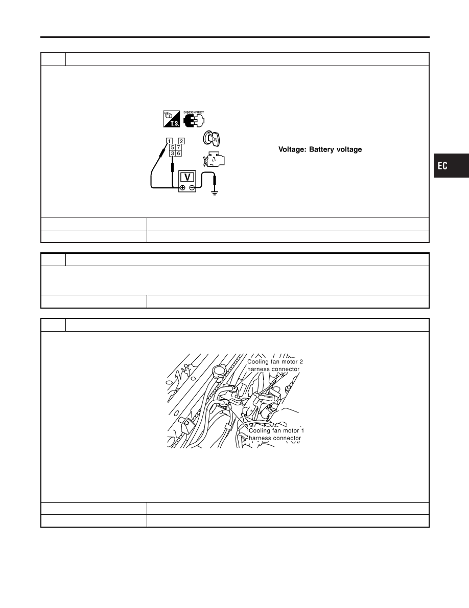
CHECK COOLING FAN POWER SUPPLY CIRCUIT

1. Turn ignition switch “OFF”.
2. Disconnect cooling fan relay-2.
3. Turn ignition switch “ON”.
4. Check voltage between cooling fan relay-2 terminals 1, 3 and ground with CONSULT-II or tester.

SEC577C

OK or NG

OK

©

GO TO 3.

NG

©

GO TO 2.

2

DETECT MALFUNCTIONING PART

Check the following.

I

Harness for open or short between cooling fan relay-2 and fuse

I

Harness for open or short between cooling fan relay-2 and fusible link

©

Repair harness or connectors.

3

CHECK COOLING FAN MOTOR CIRCUIT FOR OPEN AND SHORT

1. Turn ignition switch “OFF”.
2. Disconnect cooling fan motor-1 harness connector.

SEF854X

3. Check harness continuity between cooling fan relay-2 terminal 5 and cooling fan motor-1 terminal 2, cooling fan relay-2

terminal 6 and cooling fan motor-1 terminal 3, cooling fan relay-2 terminal 7 and body ground. Refer to Wiring Diagram.

Continuity should exist.

4. Also check harness for short to ground and short to power.

OK or NG

OK

©

GO TO 4.

NG

©

Repair open circuit or short to ground or short to power in harness or connectors.

GI

MA

EM

LC

FE

CL

MT

AT

AX

SU

BR

ST

RS

BT

HA

SC

EL

IDX

DTC P0217 COOLANT OVERTEMPERATURE ENRICHMENT PROTECTION

Diagnostic Procedure (M/T Models) (Cont’d)

EC-319

4

CHECK COOLING FAN OUTPUT SIGNAL CIRCUIT FOR OPEN AND SHORT

1. Disconnect ECM harness connector.
2. Check harness continuity between ECM terminal 12 and cooling fan relay-2 terminal 2.

Continuity should exist.

3. Also check harness for short to ground and short to power.

OK or NG

OK

©

GO TO 6.

NG

©

GO TO 5.

5

DETECT MALFUNCTIONING PART

Check the following.

I

Harness connectors E75, M6

I

Harness connectors M49, F23

I

Harness for open or short between cooling fan relay-2 and ECM

©

Repair open circuit or short to ground or short to power in harness or connectors.

6

CHECK COOLING FAN RELAY-2

Check continuity between cooling fan relay-2 terminals 3 and 5, 6 and 7 under the following conditions.

SEF591X

OK or NG

OK

©

GO TO 7.

NG

©

Replace cooling fan relay.

7

CHECK COOLING FAN MOTOR-1

Supply battery voltage between the following terminals and check operation.

SEF937XA

OK or NG

OK

©

GO TO 8.

NG

©

Replace cooling fan motor-1.

DTC P0217 COOLANT OVERTEMPERATURE ENRICHMENT PROTECTION

Diagnostic Procedure (M/T Models) (Cont’d)

EC-320

8

CHECK INTERMITTENT INCIDENT

Perform “TROUBLE DIAGNOSIS FOR INTERMITTENT INCIDENT”, EC-146.

©

INSPECTION END

Main 12 Causes of Overheating

NCEC0512

Engine

Step

Inspection item

Equipment

Standard

Reference page

OFF

1

I

Blocked radiator

I

Blocked condenser

I

Blocked radiator grille

I

Blocked bumper

I

Visual

No blocking

2

I

Coolant mixture

I

Coolant tester

50 - 50% coolant mixture See MA-11, “RECOM-

MENDED FLUIDS AND
LUBRICANTS”.

3

I

Coolant level

I

Visual

Coolant up to MAX level
in reservoir tank and
radiator filler neck

See MA-14, “Changing
Engine Coolant”.

4

I

Radiator cap

I

Pressure tester

59 - 98 kPa
(0.6 - 1.0 kg/cm

2

, 9 - 14

psi) (Limit)

See LC-9, “System
Check”.

ON*

2

5

I

Coolant leaks

I

Visual

No leaks

See LC-9, “System
Check”.

ON*

2

6

I

Thermostat

I

Touch the upper and
lower radiator hoses

Both hoses should be
hot

See LC-12, “Thermostat”
and LC-14, “Radiator”.

ON*

1

7

I

Cooling fan

I

CONSULT-II

Operating

See trouble diagnosis for
DTC P0217 (EC-291).

OFF

8

I

Combustion gas leak

I

Color checker chemi-
cal tester 4 Gas ana-
lyzer

Negative

ON*

3

9

I

Coolant temperature
gauge

I

Visual

Gauge less than 3/4
when driving

I

Coolant overflow to
reservoir tank

I

Visual

No overflow during driv-
ing and idling

See MA-14, “Changing
Engine Coolant”.

OFF*

4

10

I

Coolant return from
reservoir tank to radia-
tor

I

Visual

Should be initial level in
reservoir tank

See MA-13, “ENGINE
MAINTENANCE”.

OFF

11

I

Cylinder head

I

Straight gauge feeler
gauge

0.1 mm (0.004 in) Maxi-
mum distortion (warping)

See EM-36, “Inspection”.

12

I

Cylinder block and pis-
tons

I

Visual

No scuffing on cylinder
walls or piston

See EM-56, “Inspection”.

*1: Turn the ignition switch ON.
*2: Engine running at 3,000 rpm for 10 minutes.
*3: Drive at 90 km/h (55 MPH) for 30 minutes and then let idle for 10 minutes.
*4: After 60 minutes of cool down time.
For more information, refer to LC-15, “OVERHEATING CAUSE ANALYSIS”.

GI

MA

EM

LC

FE

CL

MT

AT

AX

SU

BR

ST

RS

BT

HA

SC

EL

IDX

DTC P0217 COOLANT OVERTEMPERATURE ENRICHMENT PROTECTION

Diagnostic Procedure (M/T Models) (Cont’d)

EC-321

On Board Diagnosis Logic

NCEC0202

When a misfire occurs, engine speed will fluctuate (vary). If the engine speed fluctuates enough to cause the
CKP sensor to vary, ECM can detect a misfire.

Sensor

Input Signal to ECM

ECM function

Crankshaft position sensor (OBD)

Engine speed

On board diagnosis of misfire

The misfire detection logic consists of the following two conditions.
1. One Trip Detection Logic (Three Way Catalyst Damage)

On the first rip that a misfire condition occurs that can damage the three way catalyst (TWC) due to
overheating, the MIL will blink.
When a misfire condition occurs, the ECM monitors the CKP sensor (OBD) signal every 200 engine revo-
lutions for a change.
When the misfire condition decreases to a level that will not damage the TWC, the MIL will turn off.
If another misfire condition occurs that can damage the TWC on a second trip, the MIL will blink.
When the misfire condition decreases to a level that will not damage the TWC, the MIL will remain on.
If another misfire condition occurs that can damage the TWC, the MIL will begin to blink again.

2. Two Trip Detection Logic (Exhaust quality deterioration)

For misfire conditions that will not cause damage to the TWC (but will affect vehicle emissions), the MIL
will only light when the misfire is detected on a second trip. During this condition, the ECM monitors the
CKP sensor (OBD) signal every 1,000 engine revolutions.
A misfire malfunction can be detected on any one cylinder or on-multiple cylinders.

DTC No.

Malfunction is detected when ...

Check Items (Possible Cause)

P0300

I

Multiple cylinders misfire.

I

Improper spark plug

I

Insufficient compression

I

Incorrect fuel pressure

I

EGR volume control valve

I

The injector circuit is open or shorted

I

Injectors

I

Intake air leak

I

The ignition secondary circuit is open or shorted

I

Lack of fuel

I

Drive plate/Flywheel

I

Heated oxygen sensor 1 (front)

I

Incorrect distributor roter

I

Incorrect PCV hose connection

P0301

I

No. 1 cylinder misfires.

P0302

I

No. 2 cylinder misfires.

P0303

I

No. 3 cylinder misfires.

P0304

I

No. 4 cylinder misfires.

SEF058Y

DTC Confirmation Procedure

NCEC0203

CAUTION:

Always drive vehicle at a safe speed.
NOTE:
If “DTC Confirmation Procedure” has been previously conducted,
always turn ignition switch “OFF” and wait at least 10 seconds
before conducting the next test.

With CONSULT-II

1)

Turn ignition switch “ON”, and select “DATA MONITOR” mode
with CONSULT-II.

2)

Start engine and warm it up to normal operating temperature.

DTC P0300 - P0304 NO. 4 - 1 CYLINDER MISFIRE, MULTIPLE CYLINDER

MISFIRE

On Board Diagnosis Logic

EC-322


Content   ..  225  226  227  228   ..