Infiniti G20 (P11). Manual - part 218
3
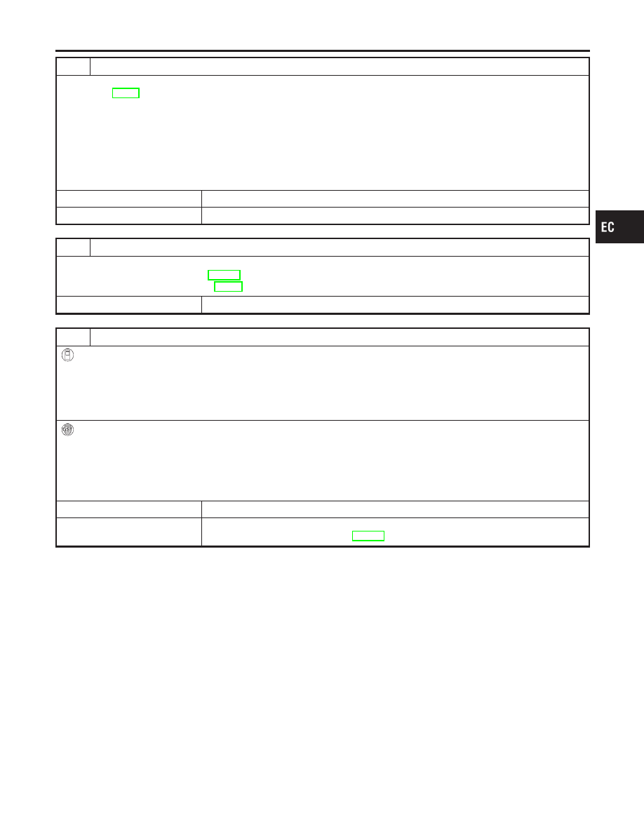
CHECK FUEL PRESSURE
1. Release fuel pressure to zero.
Refer to EC-50.
2. Install fuel pressure gauge and check fuel pressure.
At idling:
When fuel pressure regulator valve vacuum hose is connected.
Approximately 235 kPa (2.4 kg/cm
2
, 34 psi)
When fuel pressure regulator valve vacuum hose is disconnected.
Approximately 294 kPa (3.0 kg/cm
2
, 43 psi)
OK or NG
OK
©
GO TO 5.
NG
©
GO TO 4.
4
DETECT MALFUNCTIONING PART
Check the following.
I
Fuel pump and circuit (Refer to EC-605.)
I
Fuel pressure regulator (Refer to EC-51.)
©
Repair or replace.
5
CHECK MASS AIR FLOW SENSOR
With CONSULT-II
1. Install all removed parts.
2. Check “MASS AIR FLOW” in “DATA MONITOR” mode with CONSULT-II.
at idling: 2.5 - 5.0 g·m/sec
at 2,500 rpm: 7.1 - 12.5 g·m/sec
With GST
1. Install all removed parts.
2. Check mass air flow sensor signal in MODE 1 with GST.
at idling: 2.5 - 5.0 g·m/sec
at 2,500 rpm: 7.1 - 12.5 g·m/sec
OK or NG
OK
©
GO TO 6.
NG
©
Check connectors for rusted terminals or loose connections in the mass air flow sensor
circuit or engine grounds. Refer to EC-154.
GI
MA
EM
LC
FE
CL
MT
AT
AX
SU
BR
ST
RS
BT
HA
SC
EL
IDX
DTC P0172 FUEL INJECTION SYSTEM FUNCTION (RICH SIDE)
Diagnostic Procedure (Cont’d)
EC-283