Infiniti G20 (P11). Manual - part 213
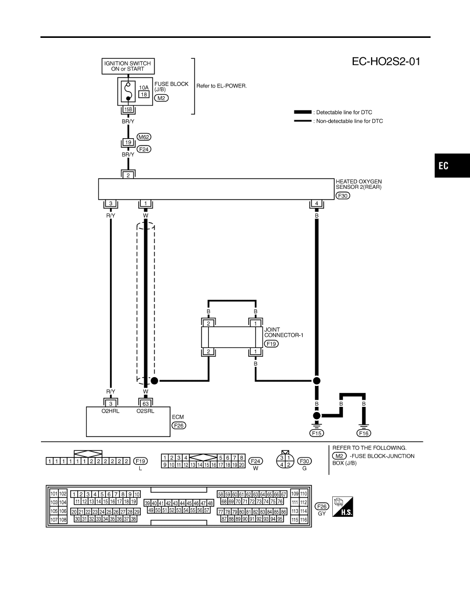
Wiring Diagram
NCEC0177
TEC839
GI
MA
EM
LC
FE
CL
MT
AT
AX
SU
BR
ST
RS
BT
HA
SC
EL
IDX
DTC P0140 HEATED OXYGEN SENSOR 2 (REAR) (HIGH VOLTAGE)
Wiring Diagram
EC-263
|
|
|
Wiring Diagram NCEC0177 TEC839 GI MA EM LC FE CL MT AT AX SU BR ST RS BT HA SC EL IDX DTC P0140 HEATED OXYGEN SENSOR 2 (REAR) (HIGH VOLTAGE) Wiring Diagram EC-263 |