Infiniti G20 (P11). Manual - part 199


  Index      Infiniti     Infiniti G20 (P11) - service repair manual 1999-2002 year


Search            


Content   ..  197  198  199  200   ..


Infiniti G20 (P11). Manual - part 199


2

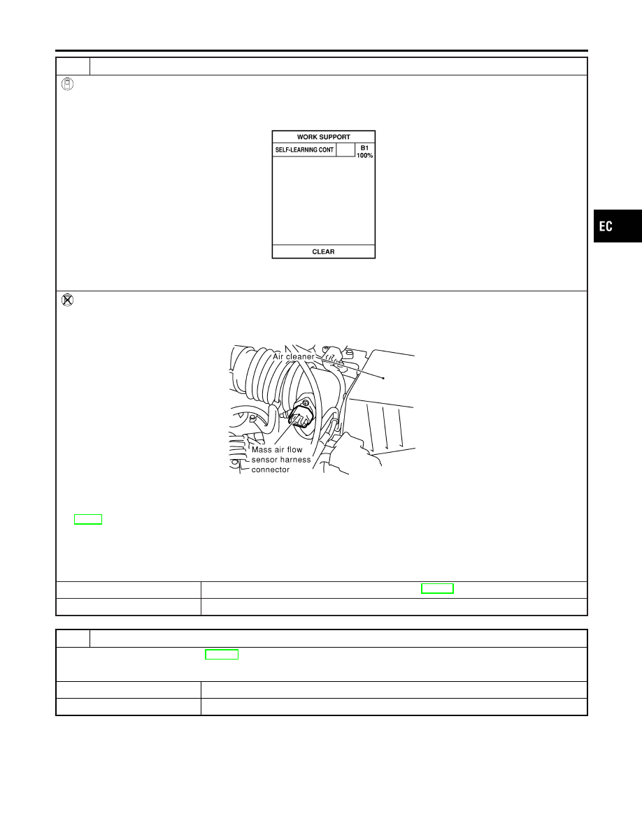
CLEAR THE SELF-LEARNING DATA.

With CONSULT-II

1. Start engine and warm it up to normal operating temperature.
2. Select “SELF-LEARNING CONT” in “WORK SUPPORT” mode with CONSULT-II.
3. Clear the self-learning control coefficient by touching “CLEAR”.

SEF215Z

4. Run engine for at least 10 minutes at idle speed.

Is the 1st trip DTC P0171 detected? Is it difficult to start engine?

Without CONSULT-II

1. Start engine and warm it up to normal operating temperature.
2. Turn ignition switch “OFF”.
3. Disconnect mass air flow sensor harness connector, and restart and run engine for at least 3 seconds at idle speed.

SEF840X

4. Stop engine and reconnect mass air flow sensor harness connector.
5. Make sure 1st trip DTC P0100 is displayed.
6. Erase the 1st trip DTC memory. Refer to “HOW TO ERASE EMISSION-RELATED DIAGNOSTIC INFORMATION”,

EC-79.

7. Make sure DTC P0000 is displayed.
8. Run engine for at least 10 minutes at idle speed.

Is the 1st trip DTC P0171 detected? Is it difficult to start engine?

Yes or No

Yes

©

Perform trouble diagnosis for DTC P0171. Refer to EC-272.

No

©

GO TO 3.

3

CHECK HEATED OXYGEN SENSOR 1 HEATER (FRONT)

Refer to “Component Inspection”, EC-236.

OK or NG

OK

©

GO TO 4.

NG

©

Replace heated oxygen sensor 1 (front).

GI

MA

EM

LC

FE

CL

MT

AT

AX

SU

BR

ST

RS

BT

HA

SC

EL

IDX

DTC P0131 HEATED OXYGEN SENSOR 1 (FRONT) (LEAN SHIFT

MONITORING)

Diagnostic Procedure (Cont’d)

EC-207

4

CHECK HEATED OXYGEN SENSOR 1 (FRONT)

Refer to “Component Inspection”, EC-208.

OK or NG

OK

©

GO TO 5.

NG

©

Replace heated oxygen sensor 1 (front).

5

CHECK SHIELD CIRCUIT

1. Turn ignition switch “OFF”.
2. Disconnect joint connector-1.
3. For circuit, refer to “DTC P0130 HEATED OXYGEN SENSOR 1 (FRONT) (CIRCUIT)”, EC-199.
4. Check the following.

I

Continuity between joint connector-1 terminal 2 and ground

I

Joint connector-1
(Refer to EL-274, “HARNESS LAYOUT”.)

Continuity should exist.

5. Also check harness for short to power.
6. Then reconnect joint connector-1.

OK or NG

OK

©

GO TO 6.

NG

©

Repair open circuit or short to power in harness or connectors.

6

CHECK INTERMITTENT INCIDENT

Perform “TROUBLE DIAGNOSIS FOR INTERMITTENT INCIDENT”, EC-146.
Refer to “Wiring Diagram”, EC-199, for circuit.

©

INSPECTION END

SEF646Y

SEF217YA

Component Inspection

NCEC0110

HEATED OXYGEN SENSOR 1 (FRONT)

NCEC0110S02

With CONSULT-II

1)

Start engine and warm it up to normal operating temperature.

2)

Select “MANU TRIG” in “DATA MONITOR” mode, and select
“HO2S1 (B1)” and “HO2S1 MNTR (B1)”.

3)

Hold engine speed at 2,000 rpm under no load during the fol-
lowing steps.

4)

Touch “RECORD” on CONSULT-II screen.

5)

Check the following.

I

“HO2S1 MNTR (B1)” in “DATA MONITOR” mode changes from
“RICH” to “LEAN” to “RICH” 5 times in 10 seconds.
5 times (cycles) are counted as shown below:
R = “HO2S1 MNTR (B1)”, “RICH”
L = “HO2S1 MNTR (B1)”, “LEAN”

I

“HO2S1 (B1)” voltage goes above 0.6V at least once.

I

“HO2S1 (B1)” voltage goes below 0.3V at least once.

I

“HO2S1 (B1)” voltage never exceeds 1.0V.

CAUTION:

I

Discard any heated oxygen sensor which has been
dropped from a height of more than 0.5 m (19.7 in) onto a
hard surface such as a concrete floor; use a new one.

DTC P0131 HEATED OXYGEN SENSOR 1 (FRONT) (LEAN SHIFT

MONITORING)

Diagnostic Procedure (Cont’d)

EC-208

I

Before installing new oxygen sensor, clean exhaust sys-
tem threads using Oxygen Sensor Thread Cleaner tool
J-43897-18 or J-43897-12 and approved anti-seize lubri-
cant.

SEF648Y

SEF011X

Without CONSULT-II

1)

Start engine and warm it up to normal operating temperature.

2)

Set voltmeter probes between ECM terminal 62 [Heated oxy-
gen sensor 1 (front) signal] and engine ground.

3)

Check the following with engine speed held at 2,000 rpm con-
stant under no load.

I

The voltage fluctuates between 0 to 0.3V and 0.6 to 1.0V more
than five times within 10 seconds.
1 time: 0 - 0.3V

0.6 - 1.0V

0 - 0.3V

2 times: 0 - 0.3V

0.6 - 1.0V

0 - 0.3V

0.6 - 1.0V

0

- 0.3V

I

The maximum voltage is over 0.6V at least one time.

I

The minimum voltage is below 0.3V at least one time.

I

The voltage never exceeds 1.0V.

CAUTION:

I

Discard any heated oxygen sensor which has been
dropped from a height of more than 0.5 m (19.7 in) onto a
hard surface such as a concrete floor; use a new one.

I

Before installing new oxygen sensor, clean exhaust sys-
tem threads using Oxygen Sensor Thread Cleaner tool
J-43897-18 or J-43897-12 and approved anti-seize lubri-
cant.

GI

MA

EM

LC

FE

CL

MT

AT

AX

SU

BR

ST

RS

BT

HA

SC

EL

IDX

DTC P0131 HEATED OXYGEN SENSOR 1 (FRONT) (LEAN SHIFT

MONITORING)

Component Inspection (Cont’d)

EC-209

SEF463R

SEF288D

Component Description

NCEC0111

The heated oxygen sensor 1 (front) is placed into the exhaust
manifold. It detects the amount of oxygen in the exhaust gas com-
pared to the outside air. The heated oxygen sensor 1 (front) has a
closed-end tube made of ceramic zirconia. The zirconia generates
voltage from approximately 1V in richer conditions to 0V in leaner
conditions. The heated oxygen sensor 1 (front) signal is sent to the
ECM. The ECM adjusts the injection pulse duration to achieve the
ideal air-fuel ratio. The ideal air-fuel ratio occurs near the radical
change from 1V to 0V.

CONSULT-II Reference Value in Data Monitor
Mode

NCEC0112

Specification data are reference values.

MONITOR ITEM

CONDITION

SPECIFICATION

HO2S1 (B1)

I

Engine: After warming
up

Maintaining engine speed
at 2,000 rpm

0 - 0.3V

+,

Approx. 0.6 - 1.0V

HO2S1 MNTR (B1)

LEAN

+,

RICH

Changes more than 5 times during
10 seconds.

ECM Terminals and Reference Value

NCEC0113

Specification data are reference values and are measured between each terminal and ground.

CAUTION:

Do not use ECM ground terminals when measuring input/output voltage. Doing so may result in dam-
age to the ECM’s transistor. Use a ground other than ECM terminals, such as the ground.

TERMI-

NAL

NO.

WIRE

COLOR

ITEM

CONDITION

DATA (DC Voltage)

62

W

Heated oxygen sensor
1 (front)

[Engine is running]

I

After warming up to normal operating temperature
and engine speed is 2,000 rpm

0 - Approximately 1.0V

SEF059V

DTC P0132 HEATED OXYGEN SENSOR 1 (FRONT) (RICH SHIFT

MONITORING)

Component Description

EC-210


Content   ..  197  198  199  200   ..