Infiniti G20 (P11). Manual - part 172


  Index      Infiniti     Infiniti G20 (P11) - service repair manual 1999-2002 year


Search            


Content   ..  170  171  172  173   ..


Infiniti G20 (P11). Manual - part 172


DTC Work Support Mode

NCEC0504S0803

Test mode

Test item

Condition

Reference page

EVAPORATIVE SYSTEM

EVAP SML LEAK P0440

Refer to corresponding
trouble diagnosis for
DTC.

EC-368

EVAP SML LEAK P1440

EC-515

PURG VOL CN/V P1444

EC-517

PURGE FLOW P1447

EC-537

VC CUT/V BP/V P1491

EC-568

HEATED OXYGEN SEN-
SOR 1 (FRONT)

HO2S1 (B1) P0130

EC-196

HO2S1 (B1) P0131

EC-204

HO2S1 (B1) P0132

EC-210

HO2S1 (B1) P0133

EC-217

HEATED OXYGEN SEN-
SOR 2 (REAR)

HO2S2 (B1) P0137

EC-237

HO2S2 (B1) P0138

EC-245

HO2S2 (B1) P0139

EC-253

EGR SYSTEM

EGR SYSTEM P0400

EC-347

EGR SYSTEM P1402

EC-505

SEF705Y

SEF707X

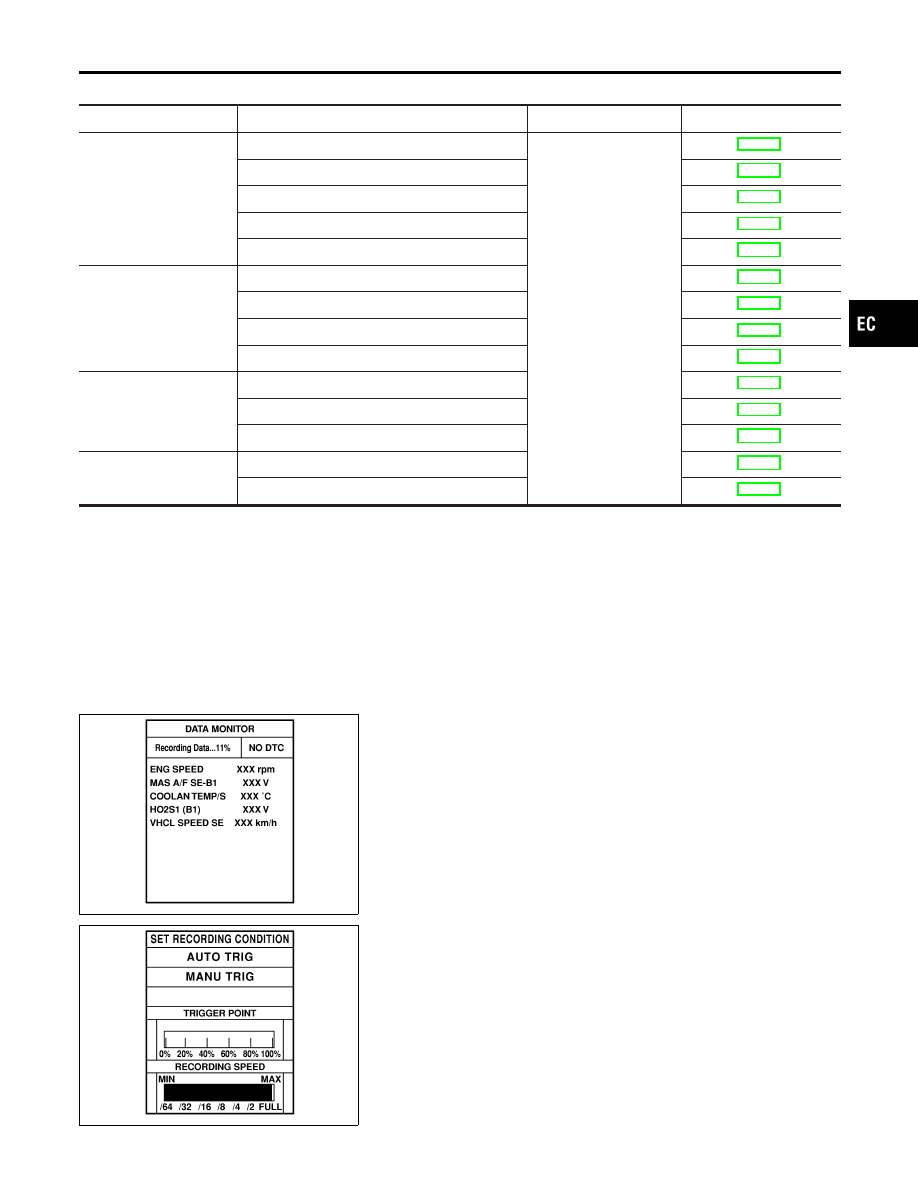
REAL TIME DIAGNOSIS IN DATA MONITOR MODE
(RECORDING VEHICLE DATA)

NCEC0504S09

CONSULT-II has two kinds of triggers and they can be selected by
touching “SETTING” in “DATA MONITOR” mode.
1)

“AUTO TRIG” (Automatic trigger):

I

The malfunction will be identified on the CONSULT-II screen in
real time.
In other words, DTC/1st trip DTC and malfunction item will be
displayed if the malfunction is detected by ECM.
At the moment a malfunction is detected by ECM, “MONITOR”
in “DATA MONITOR” screen is changed to “Recording Data ...
xx%” as shown at left, and the data after the malfunction detec-
tion is recorded. Then when the percentage reached 100%,
“REAL-TIME DIAG” screen is displayed. If “STOP” is touched
on the screen during “ Recording Data ... xx%”, “REAL-TIME
DIAG” screen is also displayed.
The recording time after the malfunction detection and the
recording speed can be changed by “TRIGGER POINT” and
“Recording Speed”. Refer to CONSULT-II OPERATION
MANUAL.

2)

“MANU TRIG” (Manual trigger):

I

DTC/1st trip DTC and malfunction item will not be displayed

GI

MA

EM

LC

FE

CL

MT

AT

AX

SU

BR

ST

RS

BT

HA

SC

EL

IDX

ON BOARD DIAGNOSTIC SYSTEM DESCRIPTION

CONSULT-II (Cont’d)

EC-99

automatically on CONSULT-II screen even though a malfunc-
tion is detected by ECM.
DATA MONITOR can be performed continuously even though
a malfunction is detected.

Use these triggers as follows:
1)

“AUTO TRIG”

I

While trying to detect the DTC/1st trip DTC by performing the
“DTC Confirmation Procedure”, be sure to select to “DATA
MONITOR (AUTO TRIG)” mode. You can confirm the malfunc-
tion at the moment it is detected.

I

While narrowing down the possible causes, CONSULT-II
should be set in “DATA MONITOR (AUTO TRIG)” mode, espe-
cially in case the incident is intermittent.
When you are inspecting the circuit by gently shaking (or twist-
ing) the suspicious connectors, components and harness in
the “DTC Confirmation Procedure”, the moment a malfunction
is found the DTC/1st trip DTC will be displayed. (Refer to
GI-25, “Incident Simulation Tests”.)

2)

“MANU TRIG”

I

If the malfunction is displayed as soon as “DATA MONITOR”
is selected, reset CONSULT-II to “MANU TRIG”. By selecting
“MANU TRIG” you can monitor and store the data. The data
can be utilized for further diagnosis, such as a comparison with
the value for the normal operating condition.

SEF714Y

ON BOARD DIAGNOSTIC SYSTEM DESCRIPTION

CONSULT-II (Cont’d)

EC-100

SEF139P

Generic Scan Tool (GST)

=NCEC0035

DESCRIPTION

NCEC0035S01

Generic Scan Tool (OBDII scan tool) complying with SAE J1978
has 7 different functions explained on the next page.
ISO9141 is used as the protocol.
The name “GST” or “Generic Scan Tool” is used in this service
manual.

SAT845J

GST INSPECTION PROCEDURE

NCEC0035S02

1.

Turn ignition switch OFF.

2.

Connect “GST” to data link connector for GST. (Data link con-
nector for GST is located under LH dash panel near the fuse
box cover.)

SEF398S

3.

Turn ignition switch ON.

4.

Enter the program according to instruction on the screen or in
the operation manual.

(*: Regarding GST screens in this section, sample screens are
shown.)

SEF416S

5.

Perform each diagnostic mode according to each service pro-
cedure.

For further information, see the GST Operation Manual of the
tool maker.

GI

MA

EM

LC

FE

CL

MT

AT

AX

SU

BR

ST

RS

BT

HA

SC

EL

IDX

ON BOARD DIAGNOSTIC SYSTEM DESCRIPTION

Generic Scan Tool (GST)

EC-101

FUNCTION

NCEC0035S03

Diagnostic test mode

Function

MODE 1

READINESS TESTS

This mode gains access to current emission-related data values, including analog
inputs and outputs, digital inputs and outputs, and system status information.

MODE 2

(FREEZE DATA)

This mode gains access to emission-related data value which were stored by ECM
during the freeze frame. [For details, refer to “Freeze Frame Data” (EC-93).]

MODE 3

DTCs

This mode gains access to emission-related power train trouble codes which were
stored by ECM.

MODE 4

CLEAR DIAG INFO

This mode can clear all emission-related diagnostic information. This includes:

I

Clear number of diagnostic trouble codes (MODE 1)

I

Clear diagnostic trouble codes (MODE 3)

I

Clear trouble code for freeze frame data (MODE 1)

I

Clear freeze frame data (MODE 2)

I

Reset status of system monitoring test (MODE 1)

I

Clear on board monitoring test results (MODE 6 and 7)

MODE 6

(ON BOARD TESTS)

This mode accesses the results of on board diagnostic monitoring tests of specific
components/systems that are not continuously monitored.

MODE 7

(ON BOARD TESTS)

This mode enables the off board test drive to obtain test results for emission-related
powertrain components/systems that are continuously monitored during normal driving
conditions.

MODE 8

This mode can close EVAP system in ignition switch “ON” position (Engine stopped).
When this mode is performed, following parts can be opened or closed.

I

EVAP canister vent control valve open

I

Vacuum cut valve bypass valve closed

In the following conditions, this mode cannot function.

I

Low ambient temperature

I

Low battery voltage

I

Engine running

I

Ignition switch “OFF”

I

Low fuel temperature

I

Too much pressure is applied to EVAP system

MODE 9

(CALIBRATION ID)

This mode enables the off-board test device to request specific vehicle information
such as Vehicle Identification Number (VIN) and Calibration IDs.

ON BOARD DIAGNOSTIC SYSTEM DESCRIPTION

Generic Scan Tool (GST) (Cont’d)

EC-102


Content   ..  170  171  172  173   ..