Infiniti G20 (P11). Manual - part 109
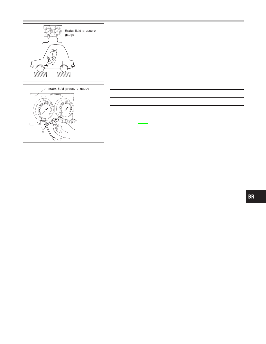
SBR822BA
SBR823BA
Inspection
NCBR0014
CAUTION:
I
Carefully monitor brake fluid level at master cylinder.
I
Use new brake fluid “DOT 3”.
I
Be careful not to splash brake fluid on painted areas; it
may cause paint damage. If brake fluid is splashed on
paint areas, wash it away with water immediately.
1.
Connect Tool to air bleeders of front and rear brakes on either
LH and RH side.
2.
Bleed air from the Tool.
3.
Check fluid pressure by depressing brake pedal.
Unit: kPa (kg/cm
2
, psi)
Applied pressure (Front brake)
7,355 (75, 1,067)
Output pressure (Rear brake)
5,100 - 5,492 (52 - 56, 739 - 796)
If output pressure is out of specification, replace dual propor-
tioning valve.
4.
Bleed air after disconnecting the Tool. Refer to “Bleeding Brake
System”, BR-8.
GI
MA
EM
LC
EC
FE
CL
MT
AT
AX
SU
ST
RS
BT
HA
SC
EL
IDX
DUAL PROPORTIONING VALVE
Inspection
BR-11