Infiniti G20 (P11). Manual - part 103
SFA221B
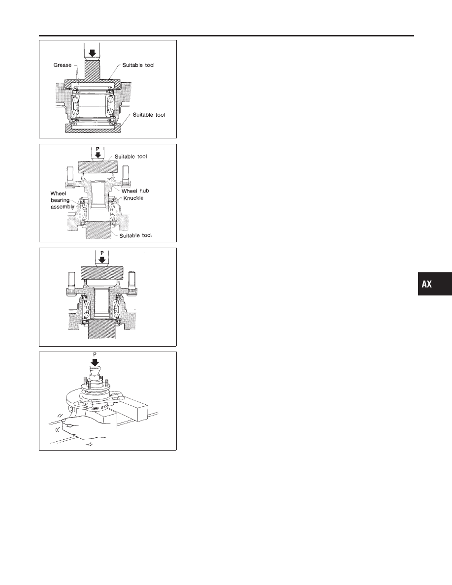
6.
Install inner grease seal.
SFA658A
7.
Press wheel hub into knuckle.
Maximum load P:
49 kN (5 ton, 5.5 US ton, 4.9 Imp ton)
Be careful not to damage grease seal.
SFA659A
8.
Check bearing operation.
a.
Add load P with press.
Load P:
34.3 - 49.0 kN
(3.5 - 5.0 ton, 3.9 - 5.5 US ton, 3.44 - 4.92 Imp ton)
SFA182A
b.
Spin knuckle several turns in both directions.
c.
Make sure that wheel bearings operate smoothly.
GI
MA
EM
LC
EC
FE
CL
MT
AT
SU
BR
ST
RS
BT
HA
SC
EL
IDX
FRONT AXLE
Wheel Hub and Knuckle (Cont’d)
AX-9