Infiniti G20 (P11). Manual - part 69
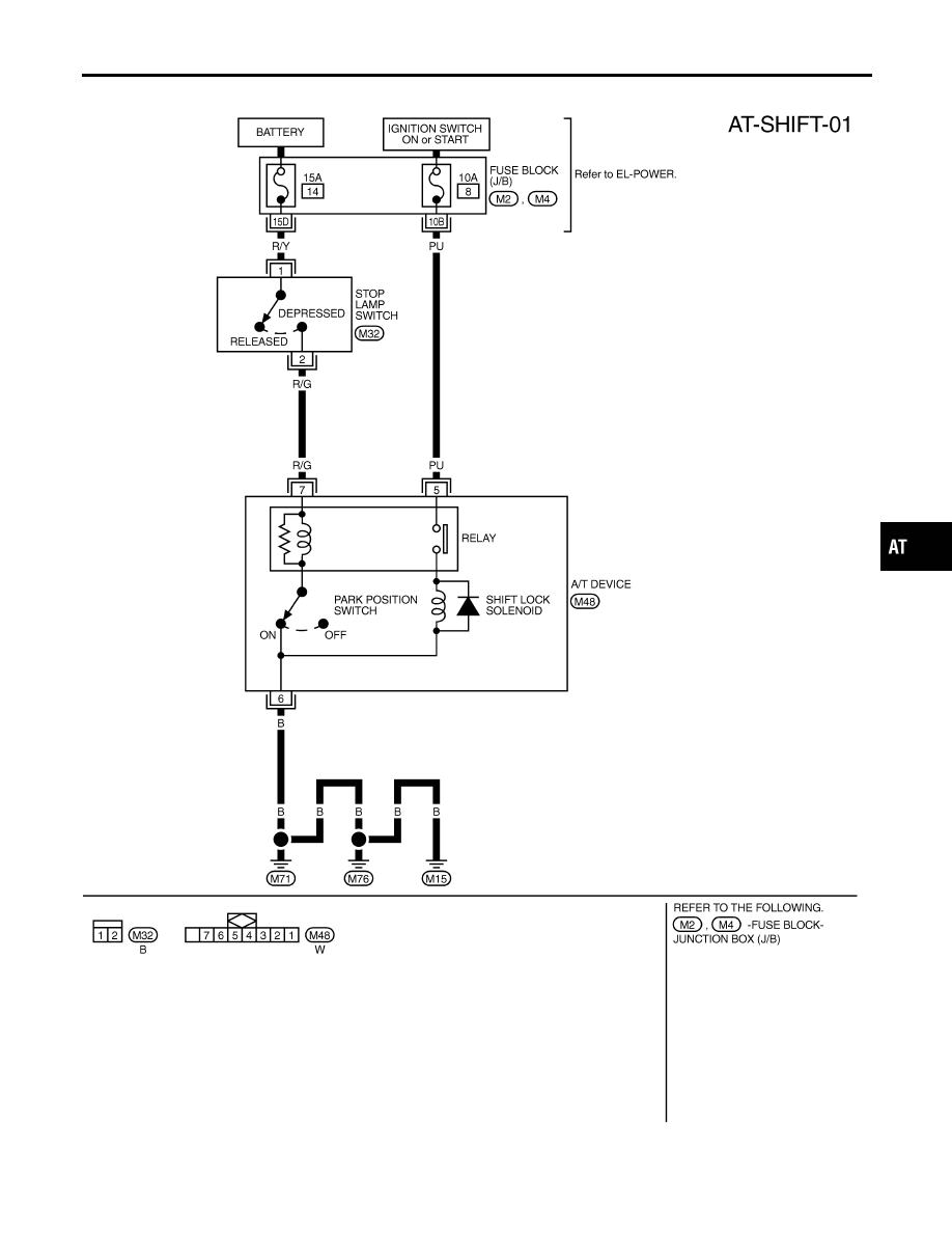
Wiring Diagram — SHIFT —
NCAT0104
TAT242
GI
MA
EM
LC
EC
FE
CL
MT
AX
SU
BR
ST
RS
BT
HA
SC
EL
IDX
A/T SHIFT LOCK SYSTEM
Wiring Diagram — SHIFT —
AT-273
|
|
|
Wiring Diagram — SHIFT — NCAT0104 TAT242 GI MA EM LC EC FE CL MT AX SU BR ST RS BT HA SC EL IDX A/T SHIFT LOCK SYSTEM Wiring Diagram — SHIFT — AT-273 |