Infiniti G20 (P11). Manual - part 45


  Index      Infiniti     Infiniti G20 (P11) - service repair manual 1999-2002 year


Search            


Content   ..  43  44  45  46   ..


Infiniti G20 (P11). Manual - part 45


Diagnostic Procedure

NCAT0062

1

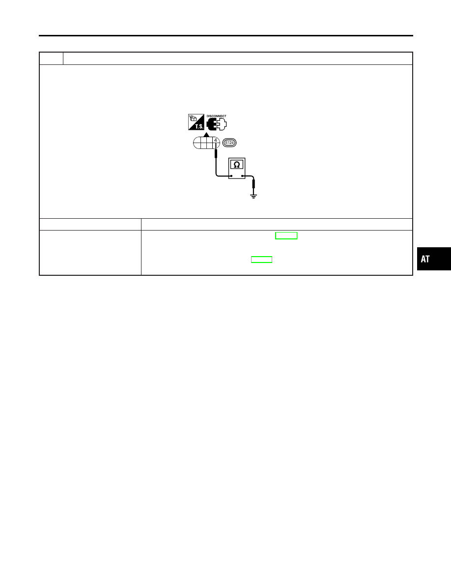
CHECK VALVE RESISTANCE

1. Turn ignition switch to “OFF” position.
2. Disconnect terminal cord assembly connector in engine compartment.
3. Check resistance between terminal 4 and ground.

Resistance:

2.5 - 5

SAT895J

OK or NG

OK

©

GO TO 2.

NG

©

1. Remove control valve assembly. Refer to AT-280.
2. Check the following items:

I

Line pressure solenoid valve
Refer to “Component Inspection”, AT-180.

I

Harness of terminal cord assembly for short or open

GI

MA

EM

LC

EC

FE

CL

MT

AX

SU

BR

ST

RS

BT

HA

SC

EL

IDX

DTC P0745 LINE PRESSURE SOLENOID VALVE

Diagnostic Procedure

AT-177

2

CHECK POWER SOURCE CIRCUIT

1. Turn ignition switch to “OFF” position.
2. Disconnect TCM harness connector.
3. Check resistance between terminal 4 and TCM harness connector terminal 2.

Resistance:

10 - 15

SAT896J

OK or NG

OK

©

GO TO 3.

NG

©

Check the following items:

I

Dropping resistor
Refer to “Component Inspection”, AT-180.

I

Harness for short or open between TCM terminal 2 and terminal cord assembly (Main
harness)

DTC P0745 LINE PRESSURE SOLENOID VALVE

Diagnostic Procedure (Cont’d)

AT-178

3

CHECK POWER SOURCE CIRCUIT

1. Turn ignition switch to “OFF” position.
2. Check resistance between terminal 4 and TCM harness connector terminal 1.

Resistance:

Approx. 0

SAT897J

If OK, check harness for short to ground and short to power.

3. Reinstall any part removed.

OK or NG

OK

©

GO TO 4.

NG

©

Repair open circuit or short to ground or short to power in harness or connectors.

4

CHECK DTC

Perform Diagnostic Trouble Code (DTC) confirmation procedure, AT-175.

OK or NG

OK

©

INSPECTION END

NG

©

1. Perform TCM input/output signal inspection.
2. If NG, recheck TCM pin terminals for damage or loose connection with harness con-

nector.

GI

MA

EM

LC

EC

FE

CL

MT

AX

SU

BR

ST

RS

BT

HA

SC

EL

IDX

DTC P0745 LINE PRESSURE SOLENOID VALVE

Diagnostic Procedure (Cont’d)

AT-179

SAT898J

Component Inspection

=NCAT0063

LINE PRESSURE SOLENOID VALVE

NCAT0063S01

I

For removal, refer to AT-280.

Resistance Check

NCAT0063S0101

I

Check resistance between two terminals.

Solenoid valve

Terminal No.

Resistance

(Approx.)

Line pressure
solenoid valve

4

Ground

2.5 - 5

SAT899J

Operation Check

NCAT0063S0102

I

Check solenoid valve by listening for its operating sound while
applying battery voltage to the terminal and ground.

SAT444J

DROPPING RESISTOR

NCAT0063S02

I

Check resistance between two terminals.

Resistance:

10 - 15

DTC P0745 LINE PRESSURE SOLENOID VALVE

Component Inspection

AT-180


Content   ..  43  44  45  46   ..