Infiniti G20 (P11). Manual - part 29
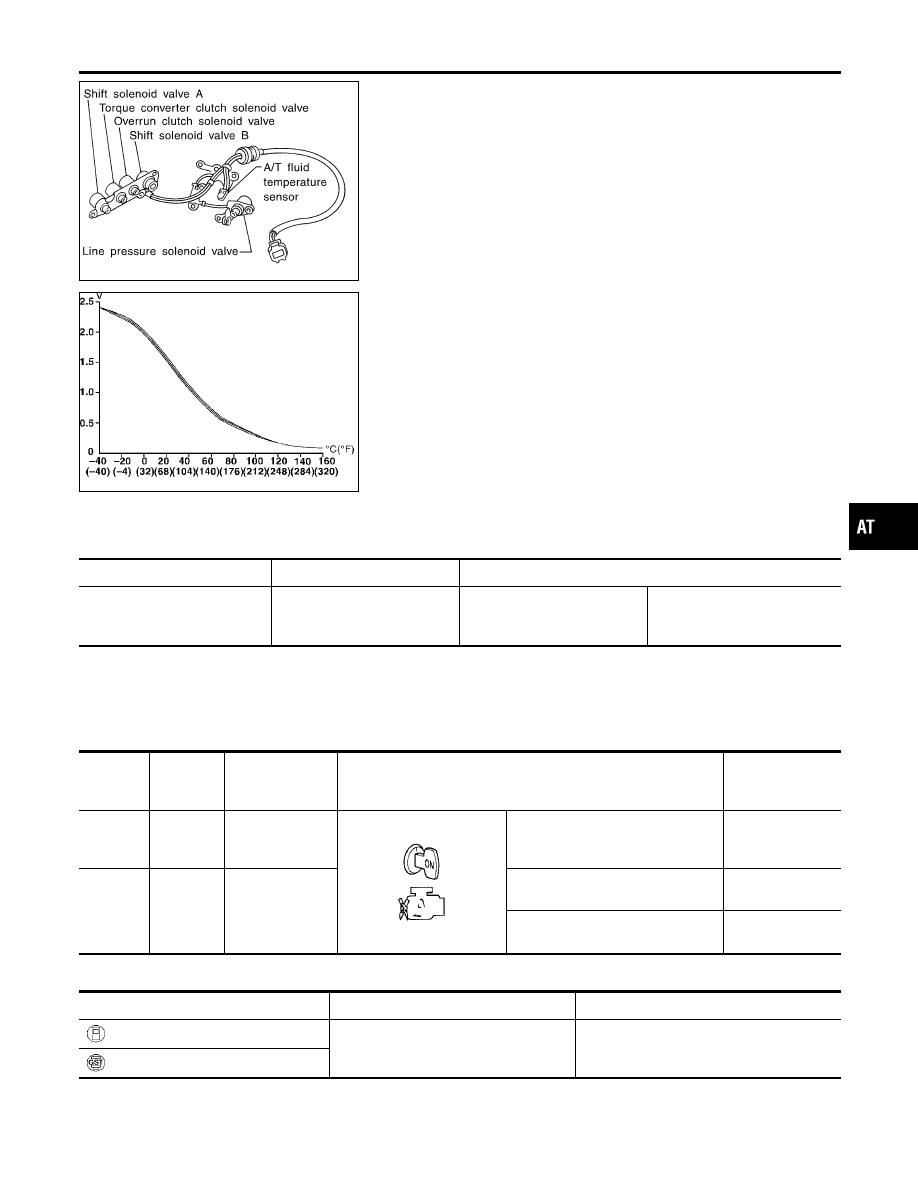
SAT283HB
SAT021J
Description
NCAT0035
The A/T fluid temperature sensor detects the A/T fluid temperature
and sends a signal to the TCM.
CONSULT-II REFERENCE VALUE IN DATA MONITOR
MODE
NCAT0035S01
Remarks: Specification data are reference values.
Monitor item
Condition
Specification (Approximately)
A/T fluid temperature sensor
Cold [20°C (68°F)]
"
Hot [80°C (176°F)]
1.5V
"
0.5V
2.5 k
Ω
"
0.3 k
Ω
TCM TERMINALS AND REFERENCE VALUE
NCAT0035S02
Remarks: Specification data are reference values.
Terminal
No.
Wire color
Item
Condition
Judgement stan-
dard
(Approx.)
42
B
Throttle position
sensor
(Ground)
—
—
47
BR
A/T fluid tempera-
ture sensor
When ATF temperature is 20°C
(68°F).
1.5V
When ATF temperature is 80°C
(176°F).
0.5V
ON BOARD DIAGNOSIS LOGIC
NCAT0035S03
Diagnostic trouble code
Malfunction is detected when ...
Check items (Possible cause)
: ATF TEMP SEN/CIRC
TCM receives an excessively low or high
voltage from the sensor.
I
Harness or connectors
(The sensor circuit is open or shorted.)
I
A/T fluid temperature sensor
: P0710
GI
MA
EM
LC
EC
FE
CL
MT
AX
SU
BR
ST
RS
BT
HA
SC
EL
IDX
DTC P0710 A/T FLUID TEMPERATURE SENSOR CIRCUIT
Description
AT-113