Infiniti FX35 / FX45. Manual - part 980


  Index      Infiniti     Infiniti FX35 / FX45 (S50) - service repair manual 2008 year


Search            


Content   ..  978  979  980  981   ..


Infiniti FX35 / FX45. Manual - part 980


WW-42

< SERVICE INFORMATION >

REAR WIPER AND WASHER SYSTEM

Removal and Installation of Rear Wiper Motor

INFOID:0000000001328591

REMOVAL

1.

Remove rear wiper arm. Refer to 

WW-40, "Removal and Installation of Rear Wiper Arm, Adjustment of

Wiper Arms Stop Location"

.

2.

Remove pivot cap, and remove nut from vehicle.

3.

Remove back door finisher. Refer to 

EI-47, "Component Parts Location"

.

4.

Disconnect rear wiper motor connector.

5.

Remove rear wiper motor mounting bolts and remove rear wiper
motor from vehicle.

CAUTION:

Never remove cushion rubber.

INSTALLATION

1.

Install rear wiper motor to the vehicle.

2.

Connect rear wiper motor connector. Turn rear wiper switch ON to operate rear wiper motor, and then turn
rear wiper switch OFF (auto stop).

3.

Install back door finisher. Refer to 

EI-47, "Component Parts Location"

.

4.

Install pivot cap, and nut.

5.

Install rear wiper arm and rear wiper arm caps. Refer to 

WW-40, "Removal and Installation of Rear Wiper

Arm, Adjustment of Wiper Arms Stop Location"

.

CAUTION:

Never drop the wiper motor or cause it to contact other parts.
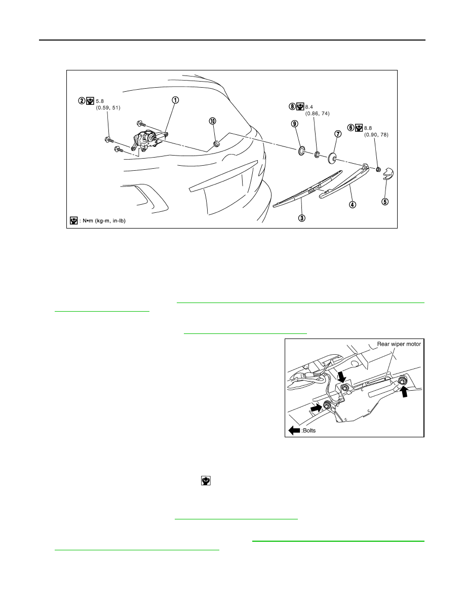
1.

Rear wiper motor

2.

Rear wiper mounting bolts

3.

Rear wiper blade

4.

Rear wiper arm

5.

Rear wiper arm cap

6.

Rear wiper arm nut

7.

Pivot cap

8.

Nut

9.

Washer

10. Cushion rubber

SKIB7578E

PKIB3588E

Rear wiper motor mounting bolts

: 5.8 N·m (0.59 kg-m, 51 in-lb)

REAR WIPER AND WASHER SYSTEM

WW-43

< SERVICE INFORMATION >

C

D

E

F

G

H

I

J

L

M

A

B

WW

N

O

P

Washer Nozzle Adjustment

INFOID:0000000001328592

• Adjust spray positions as shown in the figure.

Unit: mm (in)

• Insert a needle or suitable tool into the nozzle hole and move it to

adjust the spray position.

Washer Tube Layout

INFOID:0000000001328593

Removal and Installation of Washer Nozzle

INFOID:0000000001328594

REMOVAL

Spray position

h (height)

 (width)

φ

S

A, B

2.5 (0.098)

80 (3.15)

30 (1.18)

SKIA5088E

Adjustable range

±

 15

°

 (In any direction)

SKIA5087E

PKIC9709E

WW-44

< SERVICE INFORMATION >

REAR WIPER AND WASHER SYSTEM

1.

Remove high-mounted stop lamp. Refer to 

LT-114, "High-

Mounted Stop Lamp"

.

2.

Remove screw and remove washer nozzle from high-mounted
stop lamp.

INSTALLATION

Installation is the reverse order of removal. Adjust nozzle spray location. Refer to 

WW-43, "Washer Nozzle

Adjustment"

.

Check Valve

INFOID:0000000001328595

Blow check valve. Confirm that the air ventilates. Also confirm that
inhalation is impossible.

CAUTION:

A check valve is provided in the washer fluid line. Be careful not
to connect check valve to washer tube in the wrong direction.

Inspection of Front Wiper and Washer Switch Circuit

INFOID:0000000001328596

Refer to 

LT-104, "Combination Switch Inspection"

.

Removal and Installation of Rear Wiper and Washer Switch

INFOID:0000000001328597

Refer to 

WW-28, "Removal and Installation of Front Wiper and Washer Switch"

.

Removal and Installation of Washer Tank

INFOID:0000000001328598

Refer to 

WW-28, "Removal and Installation of Washer Tank"

.

Removal and Installation of Front and Rear Washer pump

INFOID:0000000001328599

Refer to 

WW-29, "Removal and Installation of Front and Rear Washer Pump"

.

PKIB6132E

SEL411H

POWER SOCKET

WW-45

< SERVICE INFORMATION >

C

D

E

F

G

H

I

J

L

M

A

B

WW

N

O

P

POWER SOCKET

Wiring Diagram - P/SCKT -

INFOID:0000000001328600

Removal and Installation of Front Power Socket - 1

INFOID:0000000001328601

REMOVAL

TKWM4490E


Content   ..  978  979  980  981   ..