Infiniti FX35 / FX45. Manual - part 965


  Index      Infiniti     Infiniti FX35 / FX45 (S50) - service repair manual 2008 year


Search            


Content   ..  963  964  965  966   ..


Infiniti FX35 / FX45. Manual - part 965


TROUBLE DIAGNOSES

WT-17

< SERVICE INFORMATION >

C

D

F

G

H

I

J

K

L

M

A

B

WT

N

O

P

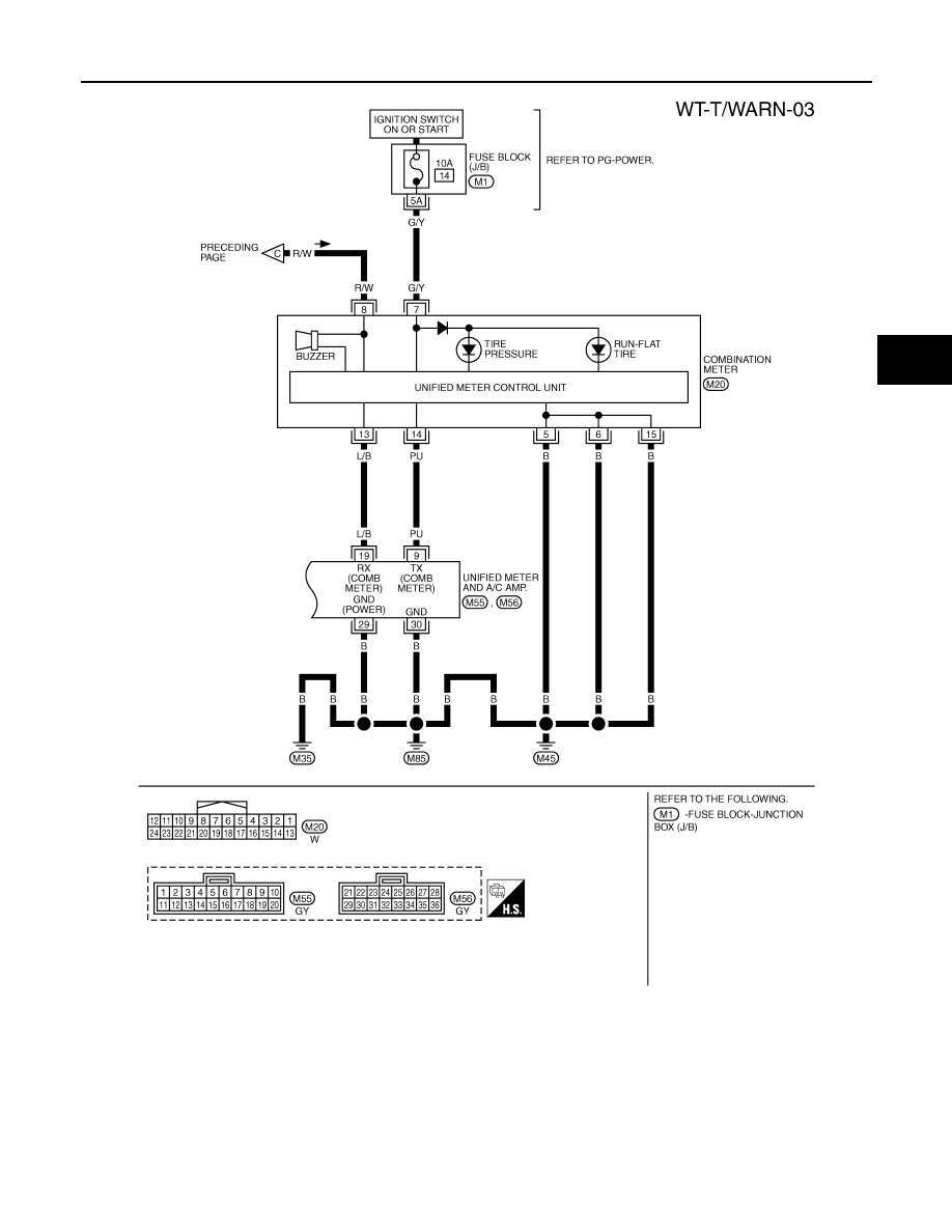
Control Unit Input/Output Signal Standard

INFOID:0000000001327581

Standards using a circuit tester and oscilloscope

TEWM0163E

WT-18

< SERVICE INFORMATION >

TROUBLE DIAGNOSES

Terminal

Item

Condition

Voltage (V)

Approx. value

+ (wire color)

15 (G)

Ground

Tire pressure warning check 
connector

Always

5V

18 (B)

Remote keyless entry receiver
(Ground)

0V

19 (R)

Remote keyless entry receiver
(Power supply)

Stand-by

Press any of the keyfob switch-
es

20 (Y)

Remote keyless entry receiver
(Signal)

Stand-by

Press any of the keyfob switch-
es

38 (W/L)

Ignition switch

Ignition switch ON or START

Battery voltage (12V)

39 (L)

CAN-H

40 (P)

CAN-L

42 (L/R) 

Battery power supply (Fuse)

Always

Battery voltage (12V)

45 (G/W)

Turn signal (left)

• Ignition switch ON
• Combination switch is turn 

signal (left) 

OCC3879D

OCC3882D

OCC3881D

OCC3880D

SKIA3009J

TROUBLE DIAGNOSES

WT-19

< SERVICE INFORMATION >

C

D

F

G

H

I

J

K

L

M

A

B

WT

N

O

P

ID Registration Procedure

INFOID:0000000001327582

ID REGISTRATION WITH ACTIVATION TOOL

This procedure must be done after replacement of a transmitter, BCM or rotating wheels.

1.

Touch “WORK SUPPORT” on “SELECT DIAG MODE” screen, and select “ID REGIST”.

2.

With the transmitter activation tool (J-45295) pushed against the
front-left transmitter position of the air valve, press and hold the
button 5 seconds.

3.

Register the IDs in order from FR LH, FR RH, RR RH to RR LH.
When ID registration of each wheel has been completed, turn
signal lamp blinks.

4.

After completing all ID registrations, press “END” to complete the procedure.

NOTE:
Be sure to register the IDs in order from FR LH, FR RH, RR RH, to RR LH, or the self-diagnostic results dis-
play will not function properly.

ID Registration without Transmitter Activation Tool

CAUTION:

This procedure must be done after replacement of a transmitter, BCM, or rotating wheels.

1.

Touch “WORK SUPPORT” on “SELECT DIAG MODE” screen, and select “ID REGIST”.

2.

Adjust the tire pressure to the values shown in the table below for ID registration, and drive the vehicle at
40 km/h (25 MPH) or more for several minutes.
NOTE:
If ID registration is unable, buzzer beeps.

3.

After completing all ID registrations, press “END” to complete the procedure.

46 (BR/W)

Ground

Turn signal (right)

• Ignition switch ON
• Combination switch is turn 

signal (right) 

49 (B)

Ground

0V

52 (B)

55 (G)

Battery power supply (F/L)

Always

Battery voltage (12V)

Terminal

Item

Condition

Voltage (V)

Approx. value

+ (wire color)

SKIA3009J

Activation tire position

Turn signal lamp

CONSULT-IIII

1

Front LH

2 times flashing

“Red”

“Green”

2

Front  RH

3

Rear  RH

4

Rear LH

SEIA0460E

Tire position

Tire pressure kPa (kg/cm

2

 , psi)

Front LH

240 (2.4, 34)

Front RH

220 (2.2, 31)

Rear RH

200 (2.0, 29)

Rear RH

180 (1.8, 26)

WT-20

< SERVICE INFORMATION >

TROUBLE DIAGNOSES

4.

Inflate all tires to proper pressure. Refer to 

WT-35, "Tire"

.

Transmitter Wake Up Operation

INFOID:0000000001327583

WITH ACTIVATION TOOL

1.

With the transmitter activation tool (J-45295) pushed against the
front-left transmitter, press the button for 5 seconds.
• When ignition switch ON, as the low tire pressure warning

lamp blinks per the following diagram, the respective transmit-
ter then must be woken up.

2.

Register the ID of wheel that low tire pressure warning lamp flashes. When wake up of registered wheel
has been completed, turn signal lamp flashes two times.

3.

After completing wake up all transmitters, make sure low tire pressure warning lamp goes out.

Self-Diagnosis

INFOID:0000000001327584

DESCRIPTION

During driving, the low tire pressure warning system receives the signal transmitted from the transmitter
installed in each wheel, and gives alarms when the tire pressure becomes low. The control unit (BCM) of this
system has pressure judgment and trouble diagnosis functions.

FUNCTION

When the low tire pressure warning system detects low inflation pressure or another unusual symptom, the
warning lamps in the combination meter comes on. To start the self-diagnostic results mode, ground terminal
of the tire pressure warning check connector. The malfunction location is indicated by the warning lamp flash-
ing and the buzzer sounds.

LOW TIRE PRESSURE WARNING LAMP DIAGNOSTIC CHART

Activation tire position

CONSULT-III

Front LH

“Red”

“Green”

Front RH

Rear RH

Rear LH

SEIA0460E

SEIA0794E


Content   ..  963  964  965  966   ..