Infiniti FX35 / FX45. Manual - part 925
SE-58
< SERVICE INFORMATION >
AUTOMATIC DRIVE POSITIONER
2.
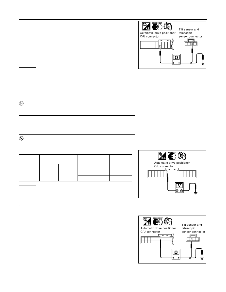
Check continuity harness between automatic drive positioner
control unit connector M49 terminals 23 and tilt sensor and tele-
scopic sensor connector M28 terminals 3.
3.
Check continuity harness between automatic drive positioner
control unit connector M49 terminals 23 and ground.
OK or NG
OK
>> Replace tilt sensor and telescopic sensor.
NG
>> Repair or replace harness between automatic drive positioner control unit and tilt sensor and tele-
scopic sensor.
Check Tilt Sensor Circuit
INFOID:0000000001328124
1.
CHECK TILT SENSOR
With CONSULT-III
With “TILT SEN” on the DATA MONITOR, operate the tilt switch to make sure voltage changes.
Without CONSULT-III
1.
Turn ignition switch OFF.
2.
Check voltage between automatic drive positioner control unit connector and ground.
OK or NG
OK
>> Tilt sensor circuit is OK.
NG
>> GO TO 2.
2.
CHECK HARNESS
1.
Disconnect automatic drive positioner control unit connector and tilt sensor and telescopic sensor connec-
tor.
2.
Check continuity harness between automatic drive positioner
control unit connector M49 terminals 7 and tilt sensor and tele-
scopic sensor connector M28 terminals 2.
3.
Check continuity harness between automatic drive positioner
control unit connector M49 terminals 7 and ground.
OK or NG
OK
>> Replace tilt sensor and telescopic sensor.
NG
>> Repair or replace harness between automatic drive positioner control unit and tilt sensor and tele-
scopic sensor.
23 (Y/B) – 3 (Y/B)
: Continuity should exist.
23 (Y/B) – Ground
: Continuity should not exist.
PIIA5079E
Monitor item
[OPERATION or UNIT]
Contents
TILT SEN
“V”
The tilt position (voltage) judged from the tilt sensor sig-
nal is displayed.
Connector
Terminals
(Wire color)
Condition
Voltage (V)
(Approx.)
(+)
(–)
M49
7 (Y/R)
Ground
Tilt top position
2
Tilt bottom position
4
PIIA5069E
7 (Y/R) – 2 (Y/R)
: Continuity should exist.
7 (Y/R) – Ground
: Continuity should not exist.
PIIA5080E