Infiniti FX35 / FX45. Manual - part 923


  Index      Infiniti     Infiniti FX35 / FX45 (S50) - service repair manual 2008 year


Search            


Content   ..  921  922  923  924   ..


Infiniti FX35 / FX45. Manual - part 923


SE-50

< SERVICE INFORMATION >

AUTOMATIC DRIVE POSITIONER

2.

CHECK FUNCTION

 With CONSULT-III

Check operation with “TILT MOTOR” in ACTIVE TEST.

OK or NG

OK

>> Steering tilt motor circuit is OK.

NG

>> GO TO 3.

3.

CHECK TILT MOTOR CIRCUIT HARNESS CONTINUITY

1.

Turn ignition switch OFF. 

2.

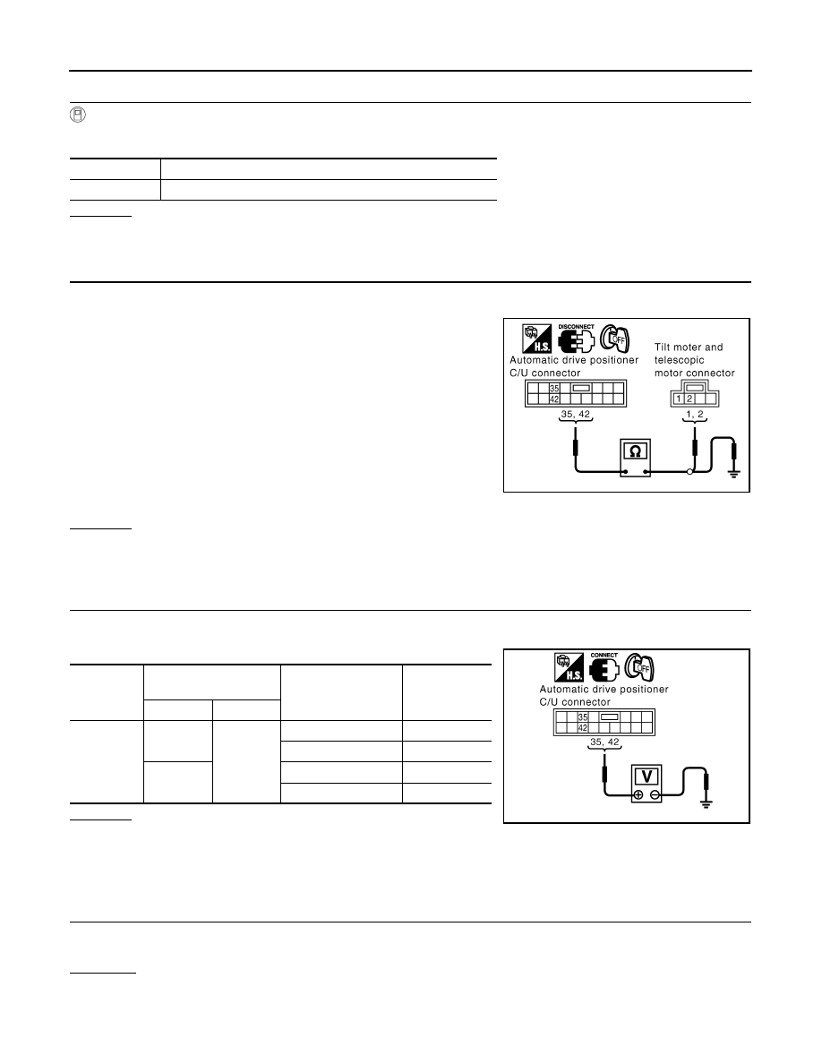
Disconnect automatic drive positioner control unit connector and tilt and telescopic motor connector.

3.

Check continuity between automatic drive positioner control unit
connector M50 terminals 35, 42 and tilt and telescopic motor
connector M27 terminals 1, 2.

4.

Check continuity between automatic drive positioner control unit
connector M50 terminals 35, 42 and ground.

OK or NG

OK

>> GO TO 4.

NG

>> Repair or replace harness between automatic drive positioner control unit and tilt and telescopic

motor.

4.

CHECK BCM OUTPUT SIGNAL

1.

Connect automatic drive positioner control unit connector and tilt and telescopic motor connector.

2.

Tilt switch operate, check voltage between automatic drive positioner control unit connector and ground.

OK or NG

OK

>> Replace tilt and telescopic motor.

NG

>> Replace automatic drive positioner control unit.

Check Driver Side Mirror Motor Circuit

INFOID:0000000001328117

1.

CHECK DOOR MIRROR FUNCTION

Check the following.
Operation malfunction caused by a foreign object caught in door mirror face edge.

OK or NG 

OK

>> • GO TO 2 (With CONSULT-III).

• GO TO 3 (Without CONSULT-III).

NG

>> Repair the malfunctioning parts, and check the symptom again.

Test item

Description

TILT MOTOR

The tilt motor is activated by receiving the drive signal.

35 (R/L) – 1 (R/L)

: Continuity should exist.

42 (R/B) – 2 (R/B)

: Continuity should exist.

35 (R/L) – Ground

: Continuity should not exist.

42 (R/B) – Ground

: Continuity should not exist.

PIIA5065E

Connector

Terminals

 (Wire color)

Tilt switch condition

Voltage (V) 

(Approx.)

(+)

(–)

M50

35 (R/L)

Ground

UP

Battery voltage

Other than above

0

42 (R/B)

DOWN

Battery voltage

Other than above

0

PIIA5067E

AUTOMATIC DRIVE POSITIONER

SE-51

< SERVICE INFORMATION >

C

D

E

F

G

H

J

K

L

M

A

B

SE

N

O

P

2.

CHECK MIRROR MOTOR

With CONSULT-III

Check the operation with “MIRROR MOTOR LH” in the ACTIVE TEST. 

OK or NG

OK

>> Driver side mirror motor circuit is OK.

NG

>> GO TO 3.

3.

CHECK DOOR MIRROR MOTOR (DRIVER SIDE) HARNESS CONTINUITY

1.

Turn ignition switch OFF.

2.

Disconnect automatic drive positioner control unit connector and door mirror (driver side) connector.

3.

Check continuity between automatic drive positioner control unit
connector M49 terminal 16, 31, 32 and door mirror (driver side)
connector D2 terminal 11, 12, 13.

4.

Check continuity between automatic drive positioner control unit
connector M49 terminal 16, 31, 32 and ground.

OK or NG

OK

>> GO TO 4.

NG

>> Repair or replace harness between automatic drive positioner control unit and door mirror (driver

side).

4.

CHECK MIRROR MOTOR SIGNAL

1.

Connect automatic drive positioner control unit and door mirror (driver side) connector.

2.

Turn ignition switch ACC.

3.

Turn changeover switch LH position.

4.

Mirror switch operate, check voltage between door mirror (driver side) connector and ground.

OK or NG

OK

>> Replace door mirror motor (driver side).

NG

>> Check the condition of the harness and the connector.

Test item

Description

MIRROR MOTOR LH

The LH mirror motor moves the mirror UP/DOWN and 
LEFT/RIGHT by receiving the drive signal.

16 (P) – 13 (P)

: Continuity should exist.

31 (R/W) – 11 (GY)

: Continuity should exist.

32 (G/B) – 12 (PU)

: Continuity should exist.

16 (P) – Ground

: Continuity should not exist.

31 (R/W) – Ground

: Continuity should not exist.

32 (G/B) – Ground

: Continuity should not exist.

PIIB8581E

Connector

Terminals

(Wire color)

Mirror switch condition

Voltage (V)

(Approx.)

(+)

(–)

D2

11 (GY)

Ground

UP

Battery voltage

Other than above

0

12 (PU)

LEFT

Battery voltage 

Other than above

0

13 (P)

DOWN or RIGHT

Battery voltage

Other than above

0

PIIB8582E

SE-52

< SERVICE INFORMATION >

AUTOMATIC DRIVE POSITIONER

Check Passenger Side Mirror Motor Circuit

INFOID:0000000001328118

1.

CHECK DOOR MIRROR FUNCTION

Check the following.
Operation malfunction caused by a foreign object caught in door mirror face edge.

OK or NG 

OK

>> • GO TO 2 (With CONSULT-III).

• GO TO 3 (WIthout CONSULT-III).

NG

>> Repair the malfunctioning parts, and check the symptom again.

2.

CHECK MIRROR MOTOR

With CONSULT-III

Check the operation with “MIRROR MOTOR RH” in the ACTIVE TEST. 

OK or NG

OK

>> Passenger side mirror motor circuit is OK.

NG

>> GO TO 3.

3.

CHECK DOOR MIRROR MOTOR (PASSENGER SIDE) HARNESS CONTINUITY

1.

Turn ignition switch OFF.

2.

Disconnect automatic drive positioner control unit connector and door mirror (passenger side) connector.

3.

Check continuity between automatic drive positioner control unit
connector M49 terminal 14, 15, 30 and door mirror (passenger
side) connector D32 terminal 11, 12, 13.

4.

Check continuity between automatic drive positioner control unit
connector M49 terminal 14, 15, 30 and ground.

OK or NG

OK

>> GO TO 4.

NG

>> Repair or replace harness between automatic drive positioner control unit and door mirror (pas-

senger side).

4.

CHECK MIRROR MOTOR SIGNAL

1.

Connect automatic drive positioner control unit and door mirror (passenger side) connector.

2.

Turn ignition switch ACC.

3.

Turn changeover switch RH position.

4.

Mirror switch operate, check voltage between door mirror (passenger side) connector and ground.

Test item

Description

MIRROR MOTOR RH

The RH mirror motor moves the mirror UP/DOWN and 
LEFT/RIGHT by receiving the drive signal.

14 (L/W) – 11 (PU)

: Continuity should exist.

15 (L/B) – 12 (OR)

: Continuity should exist.

30 (W/R) – 13 (GY)

: Continuity should exist.

14 (L/W) – Ground

: Continuity should not exist.

15 (L/B) – Ground

: Continuity should not exist.

30 (W/R) – Ground

: Continuity should not exist.

PIIB8583E

AUTOMATIC DRIVE POSITIONER

SE-53

< SERVICE INFORMATION >

C

D

E

F

G

H

J

K

L

M

A

B

SE

N

O

P

OK or NG

OK

>> Replace door mirror motor (passenger side).

NG

>> Check the condition of the harness and connector.

Check Sliding Sensor Circuit

INFOID:0000000001328119

1.

CHECK FUNCTION

 With CONSULT-III

Check operation with “SLIDE PULSE” on the DATA MONITOR to make sure the pulse changes.

 Without CONSULT-III

1.

Turn ignition switch OFF.

2.

Check signal between driver seat control unit connector and ground, with oscilloscope.

OK or NG

OK

>> Sliding sensor circuit is OK.

NG

>> GO TO 2.

2.

CHECK SLIDING SENSOR HARNESS CONTINUITY

1.

Disconnect driver seat control unit connector and sliding motor connector.

Connector

Terminals (Wire color)

Mirror switch condition

Voltage (V)

(Approx.)

(+)

(–)

D32

11 (PU)

Ground

UP

Battery voltage

Other than above

0

12 (OR)

LEFT

Battery voltage

Other than above

0

13 (G/Y)

DOWN or RIGHT

Battery voltage

Other than above

0

PIIB8582E

Monitor item 

[OPERATION or 

UNIT]

Contents

SLIDE PULSE

The seat sliding position (pulse) judged from the sliding sensor 
signal is displayed.

Connector

Terminals 

(Wire color)

Condition

Signal

(Reference value)

(+)

(–)

B152

18 (G/L)

Ground

Sliding 
motor op-
eration

PIIA6105E

PIIA3277E


Content   ..  921  922  923  924   ..