Infiniti FX35 / FX45. Manual - part 864
REAR PROPELLER SHAFT
PR-11
< SERVICE INFORMATION >
C
E
F
G
H
I
J
K
L
M
A
B
PR
N
O
P
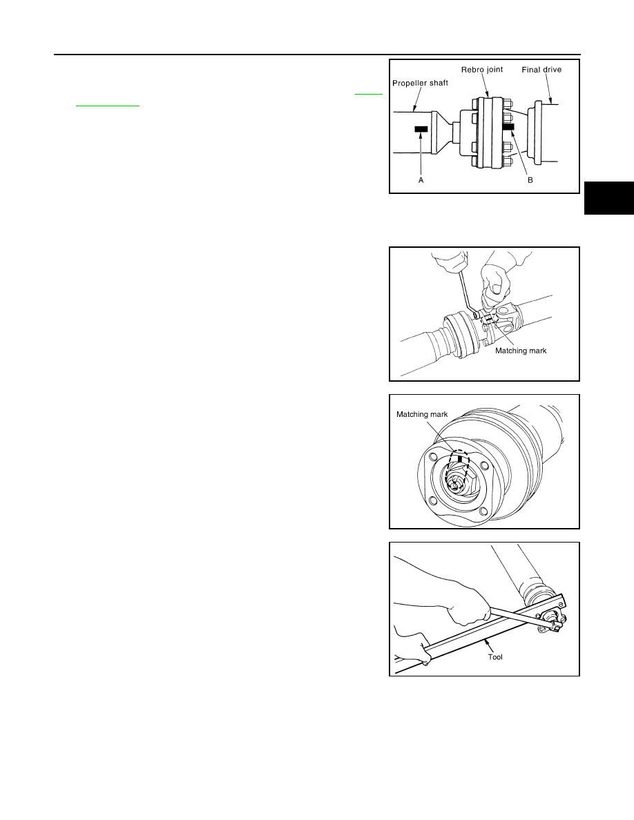
1.
Install the propeller shaft while aligning its matching mark A with
the matching mark B on the joint as close as possible.
2.
Tighten the joint bolts to the specified torque. Refer to
.
CAUTION:
Never reuse the bolts, nuts and washers.
Disassembly and Assembly of Center Bearing
INFOID:0000000001327472
DISASSEMBLY
1.
Put matching marks on propeller shaft and center flange, then
disassemble the 1st and 2nd propeller shaft.
CAUTION:
For matching mark, use paint. Never damage the propeller
shaft flange and center flange.
2.
Put matching marks onto the center flange and propeller shaft
end as shown.
CAUTION:
For matching mark, use paint. Never damage propeller shaft
end and center flange.
3.
Hold the center flange using the flange wrench, and remove the
lock nut.
4.
Remove the center flange using a commercial available bearing
puller then remove washer.
SDIA2049E
SDIA1538E
SDIA1539E
Tool number
: KV40104000 (
—
)
SDIA1540E