Infiniti FX35 / FX45. Manual - part 836
MA-24
< SERVICE INFORMATION >
ENGINE MAINTENANCE (VK45DE ENGINE)
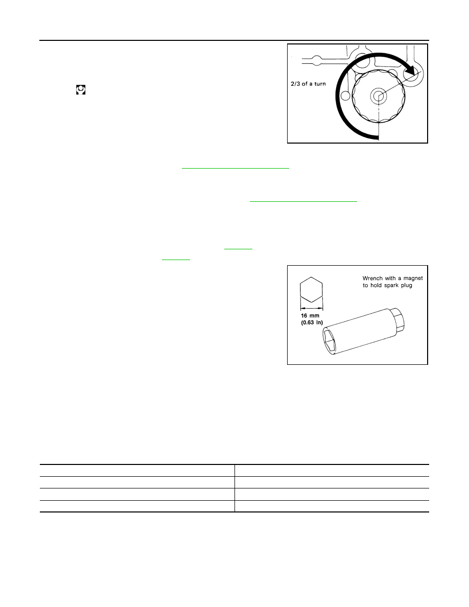
3.
Screw oil filter manually until it touches the installation surface,
then tighten it by 2/3 turn. Or tighten to specification.
INSPECTION AFTER INSTALLATION
1.
Check the engine oil level. Refer to
2.
Start engine, and check there is no leaks of engine oil.
3.
Stop engine and wait for 15 minutes.
4.
Check the engine oil level and add engine oil. Refer to
Changing Spark Plugs (Platinum-Tipped Type)
INFOID:0000000001328916
REMOVAL
1.
Remove engine cover with power tool. Refer to
2.
Remove ignition coil. Refer to
.
3.
Remove spark plug with spark plug wrench (commercial service
tool).
CAUTION:
Do not drop or shock it.
INSPECTION AFTER REMOVAL
Use standard type spark plug for normal condition.
Hot type spark plug is suitable when fouling occurs with standard type spark plug under conditions such as:
• Frequent engine starts
• Low ambient temperatures
Cold type spark plug is suitable when spark plug knock occurs with standard type spark plug under conditions such as:
• Extended highway driving
• Frequent high engine revolution
CAUTION:
• Do not drop or shock spark plug.
Oil filter:
:17.7 N·m (1.8 kg-m, 13 ft-lb)
SMA229B
SEM294A
Make
NGK
Standard type
PLFR5A-11
Hot type
PLFR4A-11
Cold type
PLFR6A-11
Gap (Nominal)
: 1.1 mm (0.043 in)