Infiniti FX35 / FX45. Manual - part 818
INTERIOR ROOM LAMP
LT-167
< SERVICE INFORMATION >
C
D
E
F
G
H
I
J
L
M
A
B
LT
N
O
P
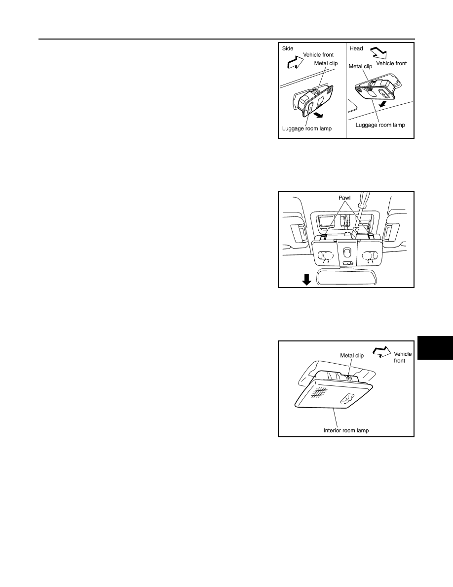
1.
Use a clip driver or similar tool to press metal clip, and remove
luggage room lamp.
2.
Disconnect luggage room lamp connector.
Installation
Installation is the reverse order of removal.
MAP LAMP
Removal
1.
Insert a clip driver or suitable tool back of map lamp and pull
down it to disengage pawl.
2.
Pull down map lamp in direction shown by the arrow in the fig-
ure.
3.
Disconnect map lamp connector and remove map lamp.
Installation
Installation is the reverse order of removal.
INTERIOR ROOM LAMP
Removal
1.
Use a suitable tool to press metal clip and remove room lamp.
2.
Disconnect interior room lamp connector.
Installation
Installation is the reverse order of removal.
PERSONAL LAMP
Removal
1.
Use a clip driver or similar tool to press metal clip, and remove personal lamp.
SKIA5579E
PKIA2847E
PKIB3525E