Infiniti FX35 / FX45. Manual - part 817


  Index      Infiniti     Infiniti FX35 / FX45 (S50) - service repair manual 2008 year


Search            


Content   ..  815  816  817  818   ..


Infiniti FX35 / FX45. Manual - part 817


INTERIOR ROOM LAMP

LT-163

< SERVICE INFORMATION >

C

D

E

F

G

H

I

J

L

M

A

B

LT

N

O

P

1.

Turn ignition switch OFF.
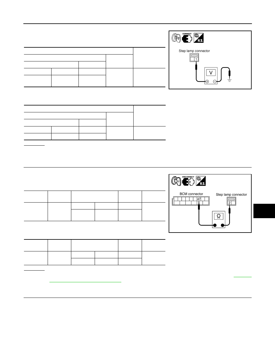
2.

Check voltage between front step lamp (driver side and passen-
ger side) harness connector and ground.

3.

Check voltage between rear step lamp (LH and RH) harness
connector and ground.

OK or NG

OK

>> GO TO 3.

NG

>> GO TO 4.

3.

CHECK STEP LAMP CIRCUIT

1.

Disconnect BCM connector and front door driver side step lamp connector.

2.

Check continuity between BCM harness connector and front
step lamp harness connector.

3.

Check continuity between BCM harness connector and rear
step lamp harness connector.

OK or NG

OK

>> Replace BCM if step lamp does not work after setting the connector again. Refer to 

BCS-13,

"Removal and Installation of BCM"

.

NG

>> Repair harness or connector.

4.

CHECK STEP LAMP CIRCUIT

1.

Disconnect BCM connector and front door driver side step lamp connector.

Terminals

Voltage

(Approx.)

(+)

(-)

Front step lamp connector

Terminal

Driver side

D9

1

Ground Battery 

voltage

Passenger 

side

D39

1

Terminals

Voltage

(Approx.)

(+)

(-)

Rear step lamp connector

Terminal

LH

D60

1

Ground Battery 

voltage

RH

D80

1

PKIA5264E

BCM 

connector

Terminal

Front step lamp

connector

Terminal

Continuity

M4

47

Driver side

D9

2

Yes

Passenger 

side

D39

2

BCM 

connector

Terminal

Rear step lamp connector

Terminal

Continuity

M4

47

LH

D80

2

Yes

RH

D60

2

PKIB3522E

LT-164

< SERVICE INFORMATION >

INTERIOR ROOM LAMP

2.

Check continuity between BCM harness connector and front
step lamp harness connector.

3.

Check continuity between BCM harness connector and rear
step lamp harness connector.

OK or NG

OK

>> Replace BCM if step lamp does not work after setting the connector again. Refer to 

BCS-13,

"Removal and Installation of BCM"

.

NG

>> Repair harness or connector.

All Interior Room Lamps Do Not Operate

INFOID:0000000001328419

1.

CHECK POWER SUPPLY CIRCUIT

1.

All interior room lamps switch are OFF.

2.

Turn ignition switch ON.

3.

Check voltage between BCM harness connector M4 terminal 41
and ground.

OK or NG

OK

>> Repair harness or connector. In a case of making a

short circuit, be sure to disconnect cable from the nega-
tive terminal repairing harness, and then reconnect.

NG

>> Replace BCM. Refer to 

BCS-13, "Removal and Installa-

tion of BCM"

.

Bulb Replacement

INFOID:0000000001328420

IGNITION KEY HOLE ILLUMINATION (without Intelligent Key)

1.

Remove combination meter. Refer to 

DI-22, "Removal and

Installation of Combination Meter"

.

2.

Remove screw and remove NATS antenna amp.

3.

Pull out ring and turn bulb socket to left to release lock.

4.

Installation is the reverse order of removal.

IGNITION KEY HOLE ILLUMINATION (with Intelligent Key)

BCM 

connector

Terminal

Front step lamp

connector

Terminal

Continuity

M4

41

Driver side

D9

1

Yes

Passenger 

side

D39

1

BCM 

connector

Terminal

Rear step lamp connector

Terminal

Continuity

M4

41

LH

D80

1

Yes

RH

D60

1

PKIB3523E

41 – Ground

: Battery voltage.

SKIA5952E

Ignition key hole illumination

: 12 V - 0.8 W

SKIA5575E

INTERIOR ROOM LAMP

LT-165

< SERVICE INFORMATION >

C

D

E

F

G

H

I

J

L

M

A

B

LT

N

O

P

1.

Remove instrument lower panel (driver side). Refer to 

IP-10

.

2.

Turn the bulb socket counterclockwise and unlock it.

3.

Installation is the reverse order of removal.

FRONT STEP LAMP

1.

Remove door finisher. Refer to 

EI-36, "Component Parts Loca-

tion"

.

2.

Insert a screwdriver in lens and remove lens.

3.

Remove bulb.

4.

Installation is the reverse order of removal.

REAR STEP LAMP

1.

Remove door finisher. Refer to 

EI-36, "Component Parts Loca-

tion"

.

2.

Insert a screwdriver in lens and remove lens.

3.

Remove bulb.

4.

Installation is the reverse order of removal.

LUGGAGE ROOM LAMP

1.

Remove luggage room lamp. Refer to 

LT-166, "Removal and

Installation"

.

2.

Remove screw from luggage room lamp.

3.

Insert a suitable tool and remove lens.

4.

Remove bulb.

5.

Installation is the reverse order of removal.

VANITY MIRROR LAMP

Ignition key hole illumination

: 12 V - 0.8 W

PKIC9733E

Step lamp

: 12 V - 5 W

SKIA5564E

Step lamp

: 12 V - 5 W

SKIA5565E

Luggage room lamp

: 12 V - 8 W

SKIA6197E

LT-166

< SERVICE INFORMATION >

INTERIOR ROOM LAMP

1.

Insert a thin screwdriver in the lens end and remove lens.

2.

Remove bulb together with substrate.

3.

Installation is the reverse order of removal.

MAP LAMP

1.

Remove lens using clip driver or suitable tool.

2.

Remove bulb.

3.

Installation is the reverse order of removal.

INTERIOR ROOM LAMP

1.

Remove interior room lamp. Refer to 

LT-166, "Removal and

Installation"

.

2.

Insert a suitable tool and remove lens.

3.

Remove bulb.

4.

Installation is the reverse order of removal.

PERSONAL LAMP

1.

Remove personal lamp. Refer to 

LT-166, "Removal and Installa-

tion"

.

2.

Remove screw from personal lamp.

3.

Insert a screwdriver or similar tool and remove lens.

4.

Remove bulb.

5.

Installation is the reverse order of removal.

Removal and Installation

INFOID:0000000001328421

LUGGAGE ROOM LAMP

Removal

Vanity mirror lamp

: 12 V - 1.32 W

PKIA7806E

Map lamp

: 12 V - 8 W

PKIA2846E

Interior room lamp

:12 V - 10 W

PKIB3637E

Personal lamp

: 12 V - 8 W

SKIA5577E


Content   ..  815  816  817  818   ..