Infiniti FX35 / FX45. Manual - part 776
TROUBLE DIAGNOSIS
LAN-81
< SERVICE INFORMATION >
[CAN]
C
D
E
F
G
H
I
J
L
M
A
B
LAN
N
O
P
CAN Communication Circuit
INFOID:0000000001328669
INSPECTION PROCEDURE
1.
CONNECTOR INSPECTION
1.
Turn the ignition switch OFF
2.
Disconnect the battery cable from the negative terminal.
3.
Disconnect all the unit connectors on CAN communication system.
4.
Check terminals and connectors for damage, bend and loose connection.
OK or NG
OK
>> GO TO 2.
NG
>> Repair the terminal and connector.
2.
CHECK HARNESS CONTINUITY (SHORT CIRCUIT)
Check the continuity between the data link connector terminals.
OK or NG
OK
>> GO TO 3.
NG
>> Check the harness and repair the root cause.
3.
CHECK HARNESS CONTINUITY (SHORT CIRCUIT)
Check the continuity between the data link connector and the ground.
OK or NG
OK
>> GO TO 4.
NG
>> Check the harness and repair the root cause.
4.
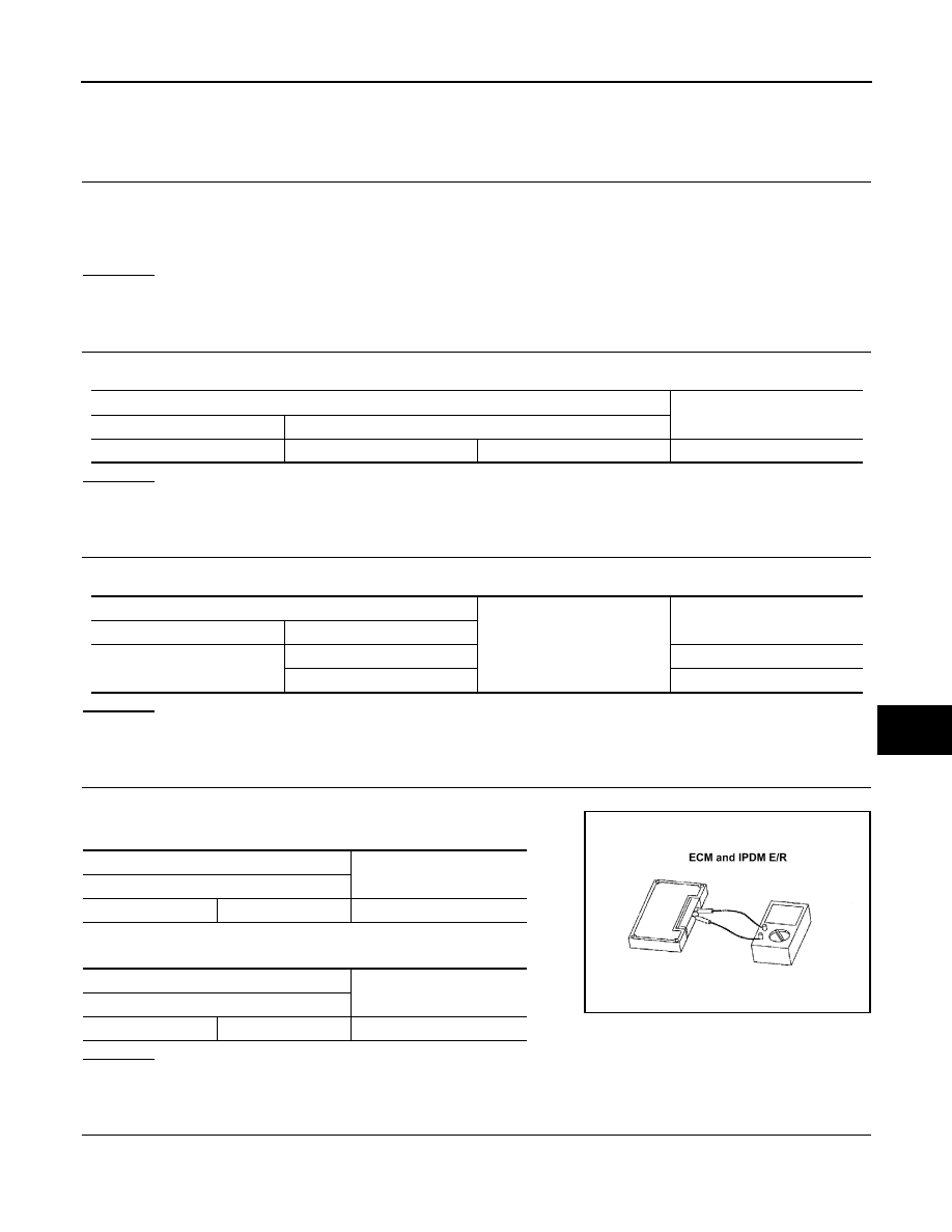
CHECK ECM AND IPDM E/R TERMINATION CIRCUIT
1.
Remove the ECM and the IPDM E/R.
2.
Check the resistance between the ECM terminals.
3.
Check the resistance between the IPDM E/R terminals.
OK or NG
OK
>> GO TO 5.
NG
>> Replace the ECM and/or the IPDM E/R.
5.
CHECK SYMPTOM
Connect all the connectors. Check if the symptoms described in the “Symptom (Results from interview with
customer)” are reproduced.
Data link connector
Continuity
Connector No.
Terminal No.
M5
6
14
No
Data link connector
Ground
Continuity
Connector No.
Terminal No.
M5
6
No
14
No
ECM
Resistance (
Ω
)
Terminal No.
94
86
Approx. 108 – 132
IPDM E/R
Resistance (
Ω
)
Terminal No.
48
49
Approx. 108 – 132
LKIA0037E