Infiniti FX35 / FX45. Manual - part 743


  Index      Infiniti     Infiniti FX35 / FX45 (S50) - service repair manual 2008 year


Search            


Content   ..  741  742  743  744   ..


Infiniti FX35 / FX45. Manual - part 743


GW-56

< SERVICE INFORMATION >

REAR DOOR GLASS AND REGULATOR

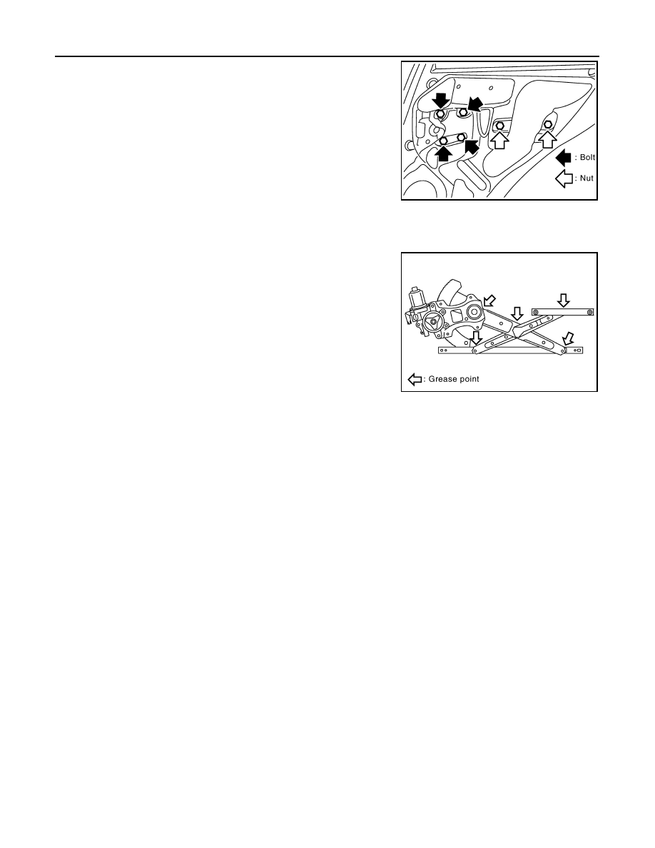
10. Remove the power window motor mounting bolts and nuts, and

remove the regulator from the panel.

11. Disconnect the connector for the regulator assembly.

Installation

Install in the reverse order of removal.

Inspection after Removal

Check the regulator assembly for the following. If a malfunction is
detected, replace or grease it.
• Gear wear
• Regulator deformation
• Spring damage
• Grease condition for each sliding part
The arrows in the figure show the application points of the body
grease. 

Disassembly and assembly

INFOID:0000000001327994

REGULATOR ASSEMBLY

Disassembly 

Remove the power window motor from the regulator assembly.

Assembly

Assemble in the reverse order of disassembly.

Fitting Inspection

INFOID:0000000001327995

• Check that the glass is securely fit into the glass run groove.
• Lower the glass slightly [approx. 10 to 20 mm (0.39 to 0.79 in)], and make sure the clearance to the sash is

parallel. Loosen the regulator mounting bolts, guide rail mounting bolts, and glass and carrier plate mounting
bolts to correct the glass position if the clearance between the glass and sash is not parallel.

PIIA4736E

PIIA4935E

INSIDE MIRROR

GW-57

< SERVICE INFORMATION >

C

D

E

F

G

H

J

K

L

M

A

B

GW

N

O

P

INSIDE MIRROR

Wiring Diagram - I/MIRR -

INFOID:0000000001327996

TIWM1683E

GW-58

< SERVICE INFORMATION >

INSIDE MIRROR

Removal and Installation

INFOID:0000000001327997

REMOVAL

1.

Remove inside mirror cover.

2.

Remove inside mirror finisher.

3.

Remove TORX bolt from mirror base.

4.

Slide the mirror base upward to remove.

5.

Disconnect the connector.

NOTE:
Insert minus deriver (A) under the inside mirror (1). Slide the inside
mirror to the upper side while pushing the pawl downward.

CAUTION:

• Do not use excessive force to remove the inside mirror

because it is inserted tightly into the mirror base.

• Do not reuse the inside mirror disassembled from mirror

base.

INSTALLATION

Install in the reverse order of removal.

COMPASS

For reset of compass, refer to 

DI-94, "System Description"

.

CAUTION:

• When inserting the inside mirror into mirror base, be sure to push the pawl until it get connected to

the mirror base.

1.

Inside mirror finisher

2.

Inside mirror 

3.

TORX bolt 

4.

Inside mirror cover

PIIA4934E

PIIB9501J

INSIDE MIRROR

GW-59

< SERVICE INFORMATION >

C

D

E

F

G

H

J

K

L

M

A

B

GW

N

O

P

• Apply Genuine Mirror Adhesive or equivalent to bonding surface of mounting bracket. Refer to 

GI-

44

.


Content   ..  741  742  743  744   ..