Infiniti FX35 / FX45. Manual - part 739
GW-40
< SERVICE INFORMATION >
POWER WINDOW SYSTEM
5.
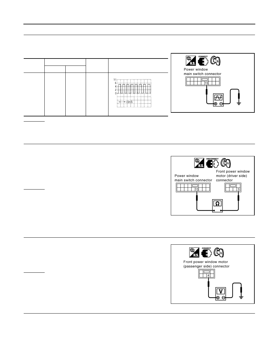
CHECK ENCODER SIGNAL
1.
Connect front power window motor (driver side) connector.
2.
Turn ignition switch ON.
3.
Check signal between power window main switch connector and ground with oscilloscope.
OK or NG
OK
>> Replace power window main switch.
NG
>> GO TO 6.
6.
CHECK HARNESS CONTINUITY 3
1.
Turn ignition switch OFF.
2.
Disconnect power window main switch and front power window motor (driver side) connector.
3.
Check continuity between power window main switch connector
D6 terminal 13 and front power window motor (driver side) con-
nector D8 terminal 3.
OK or NG
OK
>> Replace front power window motor (driver side).
NG
>> Repair or replace harness.
Check Encoder Circuit (Passenger Side)
INFOID:0000000001327984
1.
CHECK FRONT POWER WINDOW MOTOR (PASSENGER SIDE) POWER SUPPLY
1.
Turn ignition switch ON.
2.
Check voltage between front power window motor (passenger
side) connector D38 terminal 4 and ground.
OK or NG
OK
>> GO TO 3.
NG
>> GO TO 2.
2.
CHECK HARNESS CONTINUITY 1
1.
Turn ignition switch OFF.
2.
Disconnect front power window switch (passenger side) and front power window motor (passenger side)
connector.
Connec-
tor
Terminals (Wire color)
Condition
Signal
(Reference value)
(+)
(-)
D6
13 (PU)
Ground
Window
DOWN
PIIA4205E
OCC3383D
13 (PU) – 3 (PU)
: Continuity should exist.
PIIA9975E
4 (R) – Ground
: Approx.10V
PIIA9976E