Infiniti FX35 / FX45. Manual - part 714
TRANSVERSE LINK
FSU-13
< SERVICE INFORMATION >
C
D
F
G
H
I
J
K
L
M
A
B
FSU
N
O
P
TRANSVERSE LINK
Removal and Installation
INFOID:0000000001327542
REMOVAL
1.
Remove tire from vehicle with power tool.
2.
Remove undercover with power tool.
3.
Remove front cross bar.
4.
Remove cotter pin at transverse link, then loosen mounting nut.
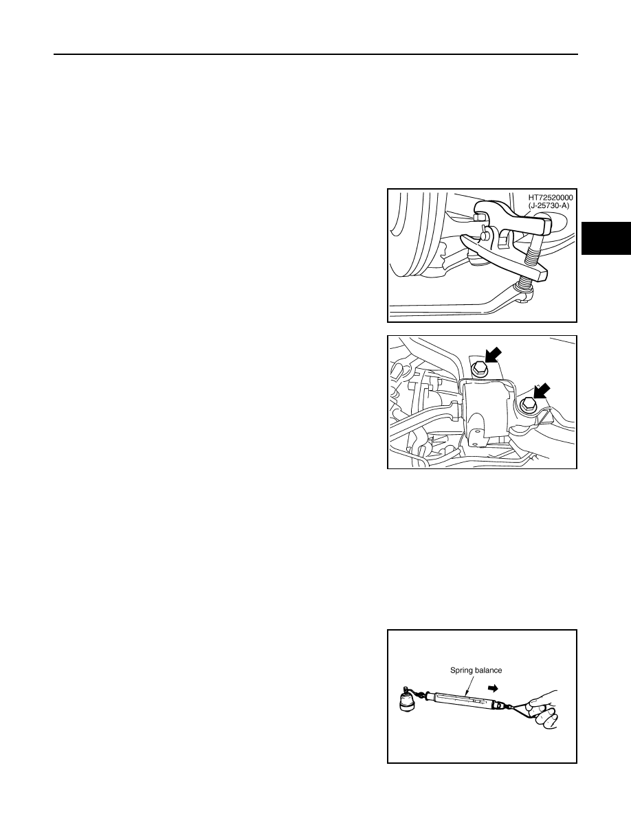
5.
Use a ball joint remover (SST) to remove transverse link from
steering knuckle. Be careful not to damage ball joint boot.
CAUTION:
Tighten temporarily mounting nut to prevent damage to
threads and to prevent ball joint remover (SST) from com-
ing off.
6.
Remove mounting bolts which are at the back of transverse link
(mounting part with body) with power tool, separate transverse
link.
7.
Remove mounting bolts which are at the front of transverse link
(mounting part with front suspension member) with power tool,
separate transverse link.
8.
Remove transverse link from vehicle.
INSPECTION AFTER REMOVAL
Visual Inspection
• Check transverse link and bushing for deformation, cracks, or damage. If any non-standard condition is
found, replace it.
• Check boot of ball joint for cracks, or other damage, and also for grease leakage. If any non-standard condi-
tion is found, replace it.
Ball Joint Inspection
Manually move ball stud to confirm it moves smoothly with no binding.
Swing Torque Inspection
NOTE:
Before measurement, move ball joint at least ten times by hand to check for smooth movement.
• Hook spring balance at ball stud. Confirm spring balance measure-
ment value is within the specifications when ball stud begins mov-
ing.
• If it is outside the specified range, replace transverse link assem-
bly.
Rotating Torque Inspection
PEIA0109E
SEIA0331E
Swing torque:
Less than 0.5
−
4.9 N·m (0.06
−
0.49 kg-m, 5
−
43 in-lb)
Measure value of spring scale:
Less than 0.5
−
4.9 N·m (0.06
−
0.49 kg-m, 5
−
43 in-lb)
SEIA0523E