Infiniti FX35 / FX45. Manual - part 713


  Index      Infiniti     Infiniti FX35 / FX45 (S50) - service repair manual 2008 year


Search            


Content   ..  711  712  713  714   ..


Infiniti FX35 / FX45. Manual - part 713


FRONT SUSPENSION ASSEMBLY

FSU-9

< SERVICE INFORMATION >

C

D

F

G

H

I

J

K

L

M

A

B

FSU

N

O

P

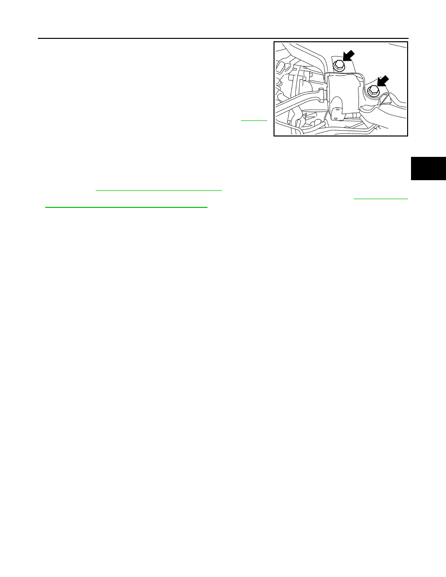
18. Remove mounting bolts which are at the back of transverse link

(mounting part with body) with power tool, separate transverse
link.

19. Remove mounting nuts between front suspension member and

body with power tool.

20. Move jack down slowly to remove front suspension member,

transverse link, stabilizer bar, drive shaft (For AWD models) and
steering knuckle from vehicle as a unit.

21. Remove transverse link from steering knuckle. Refer to 

FSU-13

.

INSTALLATION

• Refer to "Removal and Installation" for tightening torque. Install in the reverse order of removal.

NOTE:
Refer to component parts location and do not reuse non-reusable parts.

• After removing/installing or replacing suspension components and steering components, check wheel align-

ment. Refer to 

FSU-5, "Wheel Alignment Inspection"

.

• After adjusting wheel alignment, adjust neutral position of steering angle sensor. Refer to 

BRC-8, "Adjust-

ment of Steering Angle Sensor Neutral Position"

.

• Check the following item after service.
- Installation condition of wheel sensor harness.

SEIA0331E

FSU-10

< SERVICE INFORMATION >

COIL SPRING AND STRUT

COIL SPRING AND STRUT

Removal and Installation

INFOID:0000000001327540

REMOVAL

1.

Remove tires from vehicle with power tool.

2.

Remove brake hose lock plate. Then remove brake hose from
strut assembly.

3.

Remove wheel sensor harness from strut assembly.

CAUTION:

Do not pull wheel sensor harness.

4.

Remove stabilizer connecting rod upper nut with power tool,
separate stabilizer connecting rod and strut assembly.

5.

Remove fixing bolts and nuts between strut assembly and steer-
ing knuckle with power tool.

6.

Remove mounting nuts on mounting insulator bracket with
power tool, then remove strut upper plate, strut spacer and strut
from vehicle.

INSTALLATION

• Refer to 

FSU-6, "Removal and Installation"

 for tightening torque. Install in the reverse order of removal.

NOTE:
Refer to component parts location and do not reuse non-reusable parts.

• After removing/installing or replacing suspension components, check wheel alignment. Refer to 

FSU-5,

"Wheel Alignment Inspection"

.

• After adjusting wheel alignment, adjust neutral position of steering angle sensor. Refer to 

BRC-8, "Adjust-

ment of Steering Angle Sensor Neutral Position"

.

• Check the following item after service.
- Installation condition of wheel sensor harness.

SEIA0328E

SEIA0329E

SEIA0330E

COIL SPRING AND STRUT

FSU-11

< SERVICE INFORMATION >

C

D

F

G

H

I

J

K

L

M

A

B

FSU

N

O

P

• Attach strut upper plate as shown in the figure.

Disassembly and Assembly

INFOID:0000000001327541

DISASSEMBLY

NOTE:
Make sure piston rod on strut is not damaged when removing components from strut assembly.
1.

Install strut attachment (SST) to strut and fix it in a vise.

CAUTION:

When installing strut attachment (SST) to strut, wrap a shop
cloth around strut to protect it from damage.

2.

Using a spring compressor (commercial service tool), compress
coil spring between spring upper seat and spring lower seat (on
strut) until coil spring is free.

CAUTION:

Be sure spring compressor (commercial service tool) is
securely attached to coil spring. Compress coil spring.

3.

After making sure coil spring is free between spring upper seat
and spring lower seat of strut, then remove piston rod lock nut.

4.

Remove mounting insulator, mounting insulator bracket, mount-
ing bearing, spring upper seat, spring upper rubber seat, bound
bumper. Then remove coil spring and spring lower rubber seat
from strut.

5.

Gradually release spring compressor (commercial service tool), and remove coil spring.

CAUTION:

Loosen spring compressor while making sure coil spring attachment position does not move.

6.

Remove strut attachment (SST) from strut.

INSPECTION AFTER DISASSEMBLY

Strut Inspection

• Check strut for deformation, cracks, damage, and replace if necessary.
• Check piston rod for damage, uneven wear or distortion, and replace if necessary.
• Check welded and sealed areas for oil leakage, and replace if necessary.

Mounting Insulator and Rubber Parts Inspection

Check mounting insulator for cracks and rubber parts for wear. Replace them if necessary.

Coil Spring Inspection

Check coil spring for cracks, wear or damage, and replace if necessary.

ASSEMBLY

NOTE:

SEIA0334E

SEIA0296E

SEIA0297E

FSU-12

< SERVICE INFORMATION >

COIL SPRING AND STRUT

Make sure piston rod on strut is not damaged when attaching components to strut.

1.

Install strut attachment (SST) to strut and fix it in a vise.

CAUTION:

When installing strut attachment (SST) to strut, wrap a shop
cloth around strut to protect it from damage.

2.

Compress coil spring using a spring compressor (commercial service tool), and install it onto strut.

CAUTION:

• Face tube side of coil spring downward. Align lower end

to spring rubber seat as shown in the figure.

• Be sure spring compressor (commercial service tool) is

securely attached to coil spring. Compress coil spring.

3.

Apply soapy water to bound bumper and insert into mounting
insulator.

CAUTION:

Do not use machine oil.

4.

Install mounting insulator bracket, mounting bearing, bound
bumper, spring upper seat, spring upper rubber seat and spring
lower rubber seat.
• Installation position of spring upper seat is as shown in the fig-

ure.

5.

Fix mounting insulator, then tighten piston rod lock nut with
specified torque.

CAUTION:

Be careful not to deform mounting insulator bracket.

6.

Gradually release spring compressor (commercial service tool),
and remove coil spring.

CAUTION:

Loosen spring compressor while making sure coil spring
attachment position does not move.

7.

Remove strut attachment (SST) from strut.

SEIA0296E

SFA149

SEIA0247E

SEIA0298E


Content   ..  711  712  713  714   ..