Infiniti FX35 / FX45. Manual - part 701


  Index      Infiniti     Infiniti FX35 / FX45 (S50) - service repair manual 2008 year


Search            


Content   ..  699  700  701  702   ..


Infiniti FX35 / FX45. Manual - part 701


FFD-14

< SERVICE INFORMATION >

FRONT FINAL DRIVE ASSEMBLY

FRONT FINAL DRIVE ASSEMBLY

Removal and Installation (VQ35DE Models)

INFOID:0000000001327485
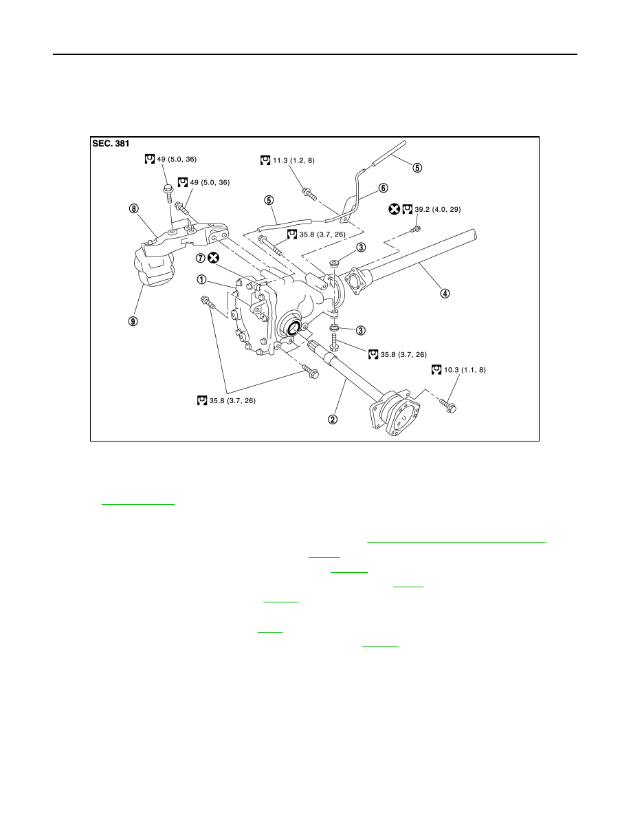
COMPONENTS

REMOVAL

1.

Remove three engine mounting bracket upper bolts. Refer to 

EM-117, "Component (AWD Models)"

.

2.

Remove three way catalyst (right bank). Refer to 

EM-26

.

3.

Remove stabilizer assembly with power tool. Refer to 

FSU-15

.

4.

Remove steering gearbox mounting bolts with power tool. Refer to 

PS-17

.

5.

Remove front drive shaft both. Refer to 

FAX-13

.

6.

Remove side shaft assembly.

7.

Remove front propeller shaft. Refer to 

PR-4

.

8.

Remove front suspension member with power tool. Refer to 

FSU-16

.

9.

Remove breather hose and tube.

10. Remove mounting bolts and remove front final drive assembly from the vehicle.

INSTALLATION

Note the following, and installation is in the reverse order of removal.
• Refer to "COMPONENTS" about each tightening torque.
• When installing the side shaft, apply multi-purpose grease to contact surface of side shaft and side shaft oil

seal.

1.

Front final drive assembly

2.

Side shaft

3.

Bushing

4.

Front propeller shaft

5.

Breather hose

6.

Breather tube

7.

Breather connector

8.

Engine mounting bracket

9.

Insulator

Refer to 

GI-8, "Component"

, for the symbols in the figure.

PDIA0789J

FRONT FINAL DRIVE ASSEMBLY

FFD-15

< SERVICE INFORMATION >

C

E

F

G

H

I

J

K

L

M

A

B

FFD

N

O

P

• Tighten mounting bolts in the order as described below when

installing front final drive assembly: side of gear carrier (1), upper
side of gear carrier (2), part of carrier cover (3), lower part of gear
carrier (4).

CAUTION:

Align the mating faces of gear carrier and oil pan for installa-
tion.

• When installing breather hoses (1) and tube (2), refer to the figure.

CAUTION:

Make sure there are no pinched or restricted areas on the
breather hose caused by bending or winding when installing
it.

- Make sure the paint mark facing up (

).

- Securely install the hose until it seats the rounded portion of the

tube (

).

- Install breather connector as shown in the figure.

- Seat the breather tube bracket end (A) to the machined face (B) of

gear carrier boss.

• When oil leaks while removing final drive assembly, check oil level

after the installation. Refer to 

FFD-8, "Changing Differential Gear

Oil"

.

Removal and Installation (VK45DE Models)

INFOID:0000000001327486

COMPONENTS

PDIA0839J

PDIA0790J

:

Vehicle front

Angle “A”:

0 - 30

°

PDIA0841J

PDIA0842E

FFD-16

< SERVICE INFORMATION >

FRONT FINAL DRIVE ASSEMBLY

REMOVAL

1.

Remove three way catalyst (right bank). Refer to 

EM-179

.

2.

Remove stabilizer assembly with power tool. Refer to 

FSU-15

.

3.

Remove steering gearbox mounting bolts with power tool. Refer to   

PS-17

.

4.

Remove front drive shaft both. Refer to 

FAX-13

.

5.

Remove side shaft assembly. 

6.

Remove front propeller shaft. Refer to 

PR-4

.

7.

Remove front suspension member with power tool. Refer to 

FSU-16

.

8.

Remove engine wire harness clamp bolts from front final drive.

9.

Remove breather hose and tube.

10. Remove mounting bolts and remove front final drive assembly from the vehicle.

INSTALLATION

Note the following, and installation is in the reverse order of removal.
• Refer to "COMPONENTS" about each tightening torque.
• When installing side shaft, apply multi-purpose grease to contact surface of side shaft and side shaft oil seal. 

1.

Front final drive assembly

2.

Side shaft

3.

Bushing

4.

Front propeller shaft

5.

Breather tube

6.

Breather hose

7.

Breather connector

8.

Harness bracket

PDIA0659E

FRONT FINAL DRIVE ASSEMBLY

FFD-17

< SERVICE INFORMATION >

C

E

F

G

H

I

J

K

L

M

A

B

FFD

N

O

P

• Tighten mounting bolts in the order as described below when

installing front final drive assembly: upper side of gear carrier (1),
part of carrier cover (2), lower part of gear carrier (3).

CAUTION:

Align the mating faces of gear carrier and oil pan for installa-
tion.

• When installing breather hoses and tube, refer to the figure.

CAUTION:

Make sure there are no pinched or restricted areas on the
breather hose caused by bending or winding when installing
it.

• Install breather connector as shown in the figure.

• When oil leaks while removing final drive assembly, check oil level

after the installation. Refer to 

FFD-8, "Checking Differential Gear

Oil"

.

Disassembly and Assembly

INFOID:0000000001327487

COMPONENTS (VQ35DE MODELS)

PDIA1213E

PDIA0661E

Angle

“A”: 22.5

°

“B”: 22.5 - 45

°

PDIA0822E


Content   ..  699  700  701  702   ..