Infiniti FX35 / FX45. Manual - part 682


  Index      Infiniti     Infiniti FX35 / FX45 (S50) - service repair manual 2008 year


Search            


Content   ..  680  681  682  683   ..


Infiniti FX35 / FX45. Manual - part 682


CYLINDER BLOCK

EM-245

< SERVICE INFORMATION >

[VK45DE]

C

D

E

F

G

H

I

J

K

L

M

A

EM

N

P

O

• Before loosening main bearing cap bolts, measure the crankshaft end play. Refer to 

EM-256, "Inspec-

tion After Disassembly"

.

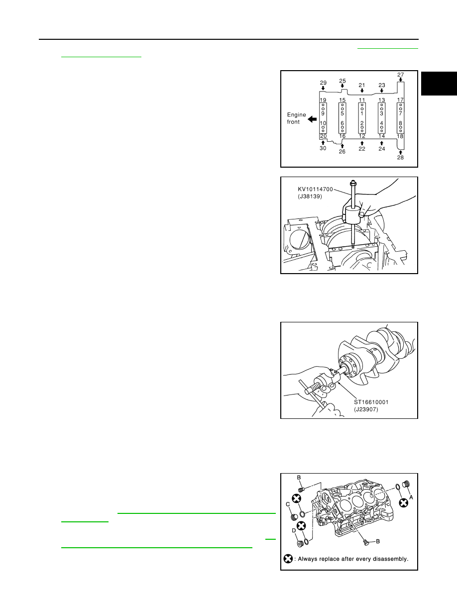
• Loosen main bearing cap bolts in several different steps.

a.

Remove cover attached to the rear left side of cylinder block
(next to the starter motor housing).
NOTE:
Bolts (No. 27 shown in the figure) are installed on the inside of
cover.

b.

Loosen side bolts (M10) starting from 30 to 21 to remove.

c.

Loosen main bearing cap sub bolts (M9) starting from 20 to 11 to
remove.

d.

Loosen main bearing cap bolts (M12) starting from 10 to 1 to
remove. 

e.

Using main bearing cap remover (SST), remove main bearing
cap. 

15. Remove crankshaft.

16. Remove main bearings and thrust bearings from cylinder block and main bearing caps.

CAUTION:

Identify installation positions, and store them without mixing them up.

17. If pilot converter must be removed, remove it from the rear end

of the crankshaft using pilot bushing puller (SST).
• It is possible to remove pilot converter without hoisting engine

with engine stand.

ASSEMBLY

1.

Fully air-blow engine coolant and engine oil passages in cylinder block, cylinder bore and crankcase to
remove any foreign material.

CAUTION:

Use a goggles to protect your eye.

2.

Install each plug to the cylinder block. (Only screwed-type plugs
are shown in the figure.)
• Apply sealant to the thread of each plug “A” and “D”. 

Use Genuine High Strength Locking Sealant or equiva-
lent. Refer to 

GI-44, "Recommended Chemical Product

and Sealant"

.

• Apply sealant to the thread of each plug “B” and “C”. 

Use Anaerobic Liquid Gasket or equivalent. Refer to 

GI-

44, "Recommended Chemical Product and Sealant"

.

• Replace copper washers with new ones.

PBIC0090E

PBIC0091E

PBIC0092E

PBIC1265E

EM-246

< SERVICE INFORMATION >

[VK45DE]

CYLINDER BLOCK

• Tighten each plug as specified below.

3.

Install main bearings and thrust bearings as follows:

a.

Remove dust, dirt and oil on the bearing mating surfaces of cylinder block and main bearing caps.

b.

Install thrust bearings to the both sides of the No. 3 journal hous-
ing on cylinder block and main bearing cap.
• Install thrust bearings with the oil groove facing the crankshaft

arm (outside). 

• Install thrust bearing with a protrusion on one end on cylinder

block, and thrust bearing with a protrusion at center on main
bearing cap. Align each protrusion with mating notch.

c.

Install main bearings paying attention to the direction.
• Main bearing with oil hole and groove goes on cylinder block.

The one without them goes on main bearing cap.

• Before installing main bearings, apply engine oil to the bearing

surface (inside). Do not apply engine oil to the back surface,
but thoroughly clean it.

• When installing, align main bearing stopper protrusion to cut-

out of cylinder block and main bearing caps.

• Ensure the oil holes on cylinder block and those on the corre-

sponding bearing are aligned.

4.

Install pilot converter to crankshaft, if removed.
• With drift [outer diameter: approx. 35 mm (1.38 in)], press-fit

as far as it will go. 

• Press-fit pilot converter with its chamfering side facing crank-

shaft as shown in the figure.

• It is possible to remove pilot converter without hoisting engine

with engine stand.

Part

Washer

Tightening torque

A

Yes

53.9 N·m (5.5 kg-m, 40 ft-lb)

B

No

19.6 N·m (2.0 kg-m, 14 ft-lb)

C

Yes

62.7 N·m (6.4 kg-m, 46 ft-lb)

D

Yes

62.7 N·m (6.4 kg-m, 46 ft-lb)

PBIC2368E

PBIC2369E

EMP0569D

SEM537E

CYLINDER BLOCK

EM-247

< SERVICE INFORMATION >

[VK45DE]

C

D

E

F

G

H

I

J

K

L

M

A

EM

N

P

O

5.

Install  crankshaft to cylinder block.
• While turning crankshaft by hand, make sure it turns smoothly. 

6.

Install main bearing caps.
• Align the identification number to the journal position to install. 
• Install the upper side of the identification number facing the

front of engine. (The number shall be read correctly from the
rear of engine.)

• Using plastic hammer or similar tool, tap them lightly to seat

them on the installation position.

NOTE:
Main bearing cap cannot be replaced as a single parts, because
it is machined together with cylinder block.

7.

Install each main bearing cap bolt as follows:

a.

Apply new engine oil to threads and seating surface of main
bearing cap bolts, and tighten all bolts temporarily.

b.

Tighten main bearing cap bolt (M12) in order of 1 to 10.

c.

Tighten main bearing cap sub bolt (M9) in order of 11 to 20.

d.

Tighten main bearing cap bolt (M12) to 40 degrees clockwise in
order of 1 to 10. (Angle tightening)

CAUTION:

Use angle wrench (SST) to check tightening angle in step
“d” and “e”. Do not make judgment by visual inspection. 

e.

Tighten main bearing cap sub bolt (M9) to 30 degrees clockwise
in order of 11 to 20. (Angle tightening)

f.

Tighten side bolt (M10) in order of 21 to 30.

• After installing main bearing cap bolts, make sure that crankshaft can be rotated smoothly.
• Check the crankshaft end play. Refer to 

EM-256, "Inspection After Disassembly"

.

g.

Install cover of cylinder block rear left side (next to the starter motor housing).

8.

Install new rear oil seal on rear oil seal retainer.
• Install new  rear oil seal so that each seal lip is oriented as

shown in the figure.

PBIC0095E

: 39.2 N·m (4.0 kg-m, 29 ft-lb)

: 29.4 N·m (3.0 kg-m, 22 ft-lb)

PBIC0090E

PBIC0096E

: 49 N·m (5.0 kg-m, 36 ft-lb)

SEM715A

EM-248

< SERVICE INFORMATION >

[VK45DE]

CYLINDER BLOCK

• Install rear oil seal to rear oil seal retainer with rear oil seal drift

(commercial service tool).

• Tap until flattened with front edge of rear oil seal retainer. Do

not damage or scratch outer circumference of oil seal.

• Make sure the garter spring is in position and seal lips not

inverted.

9.

Install rear oil seal retainer.
• Apply new engine oil to both oil seal lip and dust seal lip.
• Apply a continuous bead of liquid gasket with tube presser

(commercial service tool) to rear oil seal retainer as shown in
the figure.
Use Genuine RTV Silicone Sealant or equivalent. Refer to

GI-44, "Recommended Chemical Product and Sealant"

.

10. Install  piston to connecting rod. 

a.

Using snap ring pliers, install new snap ring to the groove of the piston rear side. 
• Insert it fully into groove to install.

b.

Install piston to connecting rod.
• Using industrial use drier or similar tool, heat piston until piston pin can be pushed in by hand without

excess force [approx. 60 to 70

°

C (140 to 158

°

F)]. From the front to the rear, insert piston pin into piston

and connecting rod.

• Assemble so that the front mark on the piston head and the oil

holes and the cylinder No. on connecting rod are positioned as
shown in the figure.

c.

Using snap ring pliers, install new snap rings to the groove of the
piston front side.
• Insert it fully into groove to install.
• After installing, make sure that connecting rod moves

smoothly.

11. Using piston ring expander (commercial service tool), install pis-

ton rings. 

CAUTION:

• When installing piston rings, be careful not to damage

piston.

• Be careful not to damage piston rings by expending them

excessively.

Rear oil seal drift

Outer diameter

: 102 mm (4.02 in)

Inner diameter

: 86 mm (3.39 in)

PBIC0097E

SBIA0391E

PBIC0099E

PBIC0087E


Content   ..  680  681  682  683   ..