Infiniti FX35 / FX45. Manual - part 665
INTAKE MANIFOLD
EM-177
< SERVICE INFORMATION >
[VK45DE]
C
D
E
F
G
H
I
J
K
L
M
A
EM
N
P
O
5.
Disconnect fuel feed hose quick connector on engine side.
Refer to
.
6.
Remove fuel damper and fuel hose assembly. Refer to
CAUTION:
• While hoses are disconnected, plug them to prevent fuel from draining.
• Do not separate fuel damper and fuel hose.
7.
Remove or disconnect harnesses, engine cover bracket (RH and LH), vacuum hose, EVAP tube and hose
and PCV hose and tube from intake manifold (upper).
8.
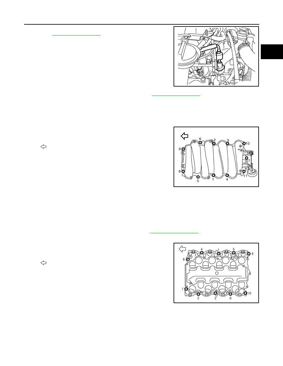
Loosen mounting bolts in reverse order as shown in the figure to
remove intake manifold (upper) with power tool.
9.
Remove electric throttle control actuator as follows:
a.
Disconnect harness connector.
b.
Loosen mounting bolts diagonally.
CAUTION:
• Handle carefully to avoid any shock to electric throttle control actuator.
• Do not disassemble.
10. Remove fuel injector and fuel tube assembly. Refer to
11. Disconnect water hoses from intake manifold adaptor.
12. Loosen mounting bolts in reverse order as shown in the figure to
remove intake manifold (lower) with power tool.
13. Remove intake manifold adaptor from intake manifold (lower).
14. Remove intake manifold gaskets.
CAUTION:
Cover engine openings to avoid entry of foreign materials.
INSPECTION AFTER REMOVAL
Surface Distortion
PBIC4552E
: Engine front
PBIC3297E
: Engine front
PBIC3298E