Infiniti FX35 / FX45. Manual - part 653


  Index      Infiniti     Infiniti FX35 / FX45 (S50) - service repair manual 2008 year


Search            


Content   ..  651  652  653  654   ..


Infiniti FX35 / FX45. Manual - part 653


CYLINDER BLOCK

EM-129

< SERVICE INFORMATION >

[VQ35DE]

C

D

E

F

G

H

I

J

K

L

M

A

EM

N

P

O

• Tighten each plug as specified below.

3.

Install oil jet.
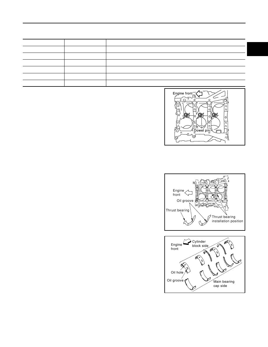
• Insert oil jet dowel pin into cylinder block dowel pin hole, and

tighten mounting bolts.

4.

Install main bearings and thrust bearings as follows:

CAUTION:

Be careful not to drop main bearing, and to scratch the surface.

a.

Remove dust, dirt, and engine oil on bearing mating surfaces of cylinder block and main bearing caps.

b.

Install thrust bearings to the both sides of the No. 3 journal hous-
ing on cylinder block and main bearing cap.
• Install thrust bearings with the oil groove facing crankshaft arm

(outside). 

• Install thrust bearing with a protrusion on one end on cylinder

block, and thrust bearing with a protrusion at center on main
bearing cap. Align each protrusion with mating notch.

c.

Install main bearings paying attention to the direction.
• Main bearing with oil hole and groove goes on cylinder block.

The one without them goes on main bearing cap.

• Before installing main bearings, apply engine oil to the bearing

surface (inside). Do not apply engine oil to the back surface,
but thoroughly clean it.

• When installing, align main bearing stopper protrusion to cut-

out of cylinder block and main bearing caps.

• Ensure the oil holes on cylinder block and those on the corre-

sponding bearing are aligned.

5.

Install crankshaft to cylinder block.
• While turning crankshaft by hand, check that it turns smoothly. 

6.

Install main bearing cap.

Part

Washer

Tightening torque

A

No

9.8 N·m (1.0 kg-m, 87 in-lb)

B

No

19.6 N·m (2.0 kg-m, 14 ft-lb)

C

No

19.6 N·m (2.0 kg-m, 14 ft-lb)

D

Yes

12.3 N·m (1.3 kg-m, 9 ft-lb)

E

Yes

62.0 N·m (6.3 kg-m, 46 ft-lb)

F

Yes

62.0 N·m (6.3 kg-m, 46 ft-lb)

PBIC0898E

PBIC0807E

PBIC2489E

EM-130

< SERVICE INFORMATION >

[VQ35DE]

CYLINDER BLOCK

• Main bearing caps are identified by identification mark cast on

them. For installation, face front mark to front side.

NOTE:
Main bearing cap cannot be replaced as a single part, because it
is machined together with cylinder block.

7.

Install main bearing beam.
• Install main bearing beam with front mark facing downward (oil pan side).
• Install main bearing beam with front mark facing front of the

engine.

8.

Install main bearing cap bolts in numerical order as shown in the
figure as follows:

a.

Inspect the outer diameter of main bearing cap bolt. Refer to

EM-138, "Inspection After Disassembly"

.

b.

Apply new engine oil to threads and seat surfaces of main bear-
ing cap bolts.

c.

Tighten main bearing cap bolts in several different steps.

d.

Turn all main bearing cap bolts 90 degrees clockwise (Angle
tightening).

CAUTION:

Use the angle wrench [SST: KV10112100 (BT8653-A)] to
check tightening angle. Do not make judgment by visual
inspection.
• After installing main bearing cap bolts, make sure that crank-

shaft can be rotated smoothly by hand.

• Check the crankshaft end play. Refer to 

EM-138, "Inspection

After Disassembly"

.

9.

Install piston to connecting rod as follows: 

a.

Using a snap ring pliers, install new snap ring to the groove of piston rear side. 
• Insert it fully into groove to install.

b.

Install piston to connecting rod.
• Using an industrial use drier or similar tool, heat piston until piston pin can be pushed in by hand without

excess force [approx. 60 to 70

°

C (140 to 158

°

F)]. From the front to the rear, insert piston pin into piston

and connecting rod.

SEM456G

PBIC0881E

 : 35.3 N·m (3.6 kg-m, 26 ft-lb)

PBIC1800E

PBIC0921E

CYLINDER BLOCK

EM-131

< SERVICE INFORMATION >

[VQ35DE]

C

D

E

F

G

H

I

J

K

L

M

A

EM

N

P

O

• Assemble so that the front mark on the piston head and the

cylinder number on connecting rod are positioned as shown in
the figure.

c.

Install new snap ring to the groove of the piston front side. 
• Insert it fully into groove to install.
• After installing, make sure that connecting rod moves

smoothly.

10. Using a piston ring expander (commercial service tool), install

piston rings.

CAUTION:

• When installing piston rings, be careful not to damage

piston.

• Be careful not to damage piston rings by expending them

excessively.

• If there is stamped mark on ring, mount it with marked side up.

NOTE:
If there is no stamp on ring, no specific orientation is required
for installation.

• Position each ring with the gap as shown in the figure referring

to the piston front mark.

• Check the piston ring side clearance. Refer to 

EM-138, "Inspection After Disassembly"

.

11. Install connecting rod bearings to connecting rod and connecting rod bearing cap.

CAUTION:

Be careful not to drop connecting rod bearing, and to scratch the surface.
• Before installing connecting rod bearings, apply engine oil to the bearing surface (inside). Do not apply

engine oil to the back surface, but thoroughly clean it. 

SEM838F

PBIC0087E

Stamped mark:

Top ring

: —

Second ring

: “R”

SEM757G

PBIC0808E

EM-132

< SERVICE INFORMATION >

[VQ35DE]

CYLINDER BLOCK

• When installing, align connecting rod bearing stopper protru-

sion with cutout of connecting rods and connecting rod bearing
caps to install. 

• Ensure the oil hole on connecting rod and that on the corre-

sponding bearing are aligned. 

12. Install piston and connecting rod assembly to crankshaft. 

• Position crankshaft pin corresponding to connecting rod to be installed onto the bottom dead center. 
• Apply engine oil sufficiently to the cylinder bore, piston and crankshaft pin journal.
• Match the cylinder position with the cylinder number on connecting rod to install. 
• Be sure that front mark on piston crown is facing front of engine.
• Using a piston ring compressor (SST) or suitable tool, install

piston with the front mark on the piston crown facing the front
of the engine.

CAUTION:

Be careful not to damage the cylinder wall and crankshaft
pin, resulting from an interference of the connecting rod big
end.

13. Install connecting rod bearing cap.

• Match the stamped cylinder number marks on connecting rod

with those on connecting rod bearing cap to install.

• Be sure that front mark on connecting rod bearing cap is fac-

ing front of the engine.

14. Tighten connecting rod bolt as follows:

a.

Inspect the outer diameter of connecting rod bolt. Refer to 

EM-138, "Inspection After Disassembly"

.

b.

Apply engine oil to the threads and seats of connecting rod bolts. 

c.

Tighten connecting rod bolts.

PBIC2067E

PBIC2945E

PBIC0809E

 : 19.6 N·m (2.0 kg-m, 14 ft-lb)


Content   ..  651  652  653  654   ..