Infiniti FX35 / FX45. Manual - part 652
CYLINDER BLOCK
EM-125
< SERVICE INFORMATION >
[VQ35DE]
C
D
E
F
G
H
I
J
K
L
M
A
EM
N
P
O
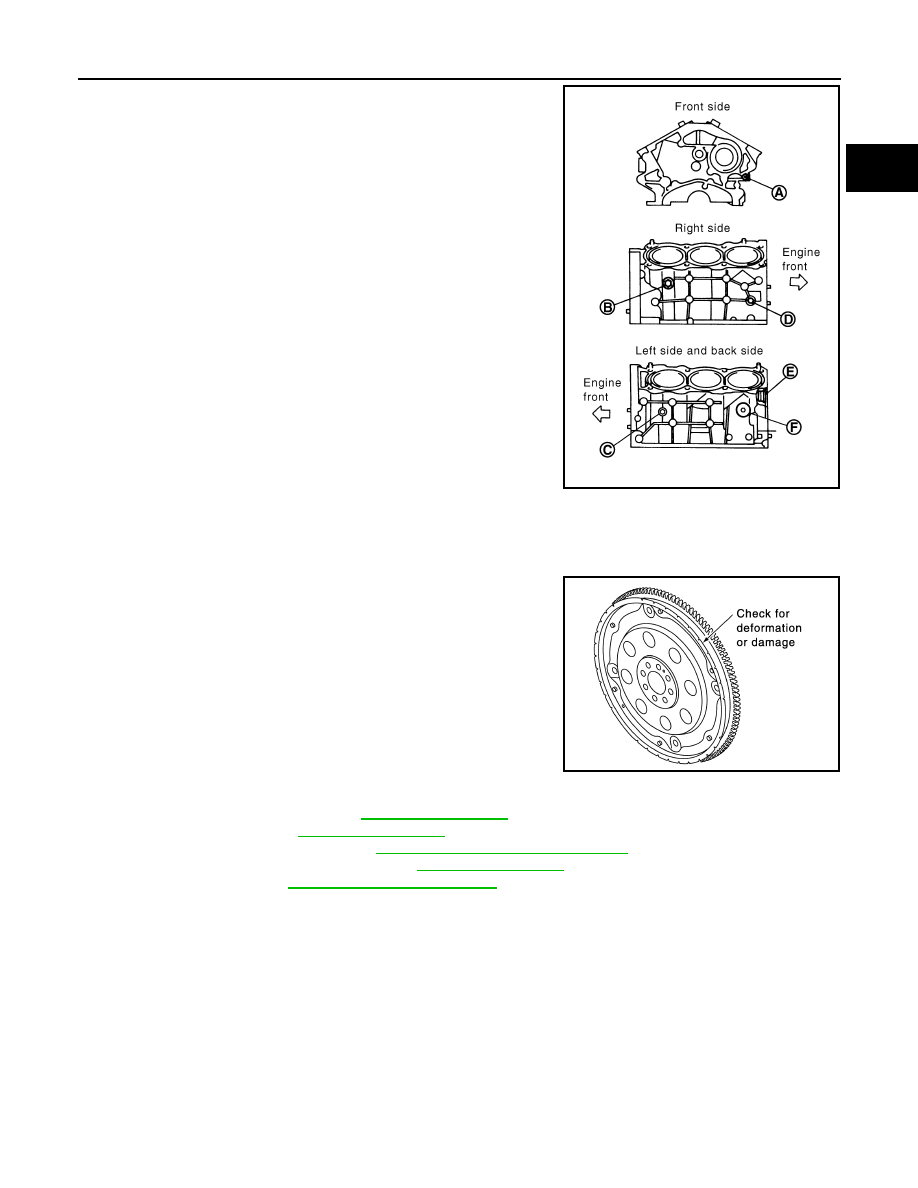
6.
Drain engine coolant by removing water drain plugs from cylin-
der block both sides at “B” and “C” and cylinder block front side
at “A” as shown in the figure.
7.
Remove drive plate with power tool. Fix crankshaft with a ring gear stopper [SST: KV1011770 (J44716)],
and remove mounting bolts.
• Loosen mounting bolts in diagonal order.
CAUTION:
• Do not disassemble drive plate.
• Never place drive plate with signal plate facing down.
• When handling signal plate, take care not to damage or
scratch it.
• Handle signal plate in a manner that prevents it from
becoming magnetized.
8.
Remove the following parts:
• Intake manifold collector: Refer to
• Intake manifold: Refer to
.
• Oil pans (lower and upper): Refer to
EM-30, "Component (2WD Models)"
.
• Front and rear timing chain case: Refer to
.
9.
Remove knock sensor.
CAUTION:
Carefully handle sensor avoiding shocks.
PBIC2610E
SEM760G