Infiniti FX35 / FX45. Manual - part 601


  Index      Infiniti     Infiniti FX35 / FX45 (S50) - service repair manual 2008 year


Search            


Content   ..  599  600  601  602   ..


Infiniti FX35 / FX45. Manual - part 601


ICC BRAKE SWITCH

EC-1165

< SERVICE INFORMATION >

[VK45DE]

C

D

E

F

G

H

I

J

K

L

M

A

EC

N

P

O

3.

Check continuity between ICC brake switch terminals 1 and 2
under the following conditions.

4.

If NG, adjust ICC brake switch installation, refer to 

BR-5

, and

perform step 3 again.

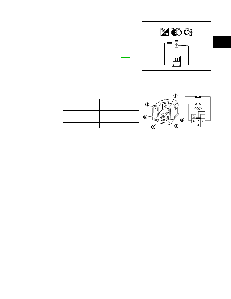
ICC BRAKE HOLD RELAY

1.

Apply 12V direct current between ICC brake hold relay terminals 1 and 2.

2.

Check continuity between relay terminals 3 and 4, 6 and 7 under
the following conditions.

3.

If NG, replace ICC brake hold relay.

Condition

Continuity

Brake pedal: Fully released

Should exist

Brake pedal: Slightly depressed

Should not exist

PBIB1536E

Condition

Between terminals

Continuity

12V direct current supply 
between terminals 1 and 2

3 and 4

Should not exist

6 and 7

Should exist

No current supply

3 and 4

Should exist

6 and 7

Should not exist

MBIB0063E

EC-1166

< SERVICE INFORMATION >

[VK45DE]

IGNITION SIGNAL

IGNITION SIGNAL

Component Description

INFOID:0000000001327068

IGNITION COIL & POWER TRANSISTOR

The ignition signal from the ECM is sent to and amplified by the power transistor. The power transistor turns
ON and OFF the ignition coil primary circuit. This ON/OFF operation induces the proper high voltage in the coil
secondary circuit.

: Vehicle front

1.

Ignition coil
(With power transistor)
(Bank 2)

2.

Ignition coil
(With power transistor)
(Bank 1)

PBIB3234E

IGNITION SIGNAL

EC-1167

< SERVICE INFORMATION >

[VK45DE]

C

D

E

F

G

H

I

J

K

L

M

A

EC

N

P

O

Wiring Diagram

INFOID:0000000001327069

Specification data are reference values and are measured between each terminal and ground.

CAUTION:

Do not use ECM ground terminals when measuring input/output voltage. Doing so may result in dam-
age to the ECM's transistor. Use a ground other than ECM terminals, such as the ground.

TBWM1359E

EC-1168

< SERVICE INFORMATION >

[VK45DE]

IGNITION SIGNAL

TER-

MI-

NAL 

NO.

WIRE 

COLOR

ITEM

CONDITION

DATA (DC Voltage)

111

W/B

ECM relay
(Self shut-off)

[Engine is running]
[Ignition switch: OFF]
• For a few seconds after turning ignition 

switch OFF

0 - 1.5V

[Ignition switch: OFF]
• More than a few seconds after turning igni-

tion switch OFF

BATTERY VOLTAGE
(11 - 14V)

119

120

R
R/B

Power supply for ECM

[Ignition switch: ON]

BATTERY VOLTAGE
(11 - 14V)


Content   ..  599  600  601  602   ..