Infiniti FX35 / FX45. Manual - part 587


  Index      Infiniti     Infiniti FX35 / FX45 (S50) - service repair manual 2008 year


Search            


Content   ..  585  586  587  588   ..


Infiniti FX35 / FX45. Manual - part 587


DTC P2122, P2123 APP SENSOR

EC-1109

< SERVICE INFORMATION >

[VK45DE]

C

D

E

F

G

H

I

J

K

L

M

A

EC

N

P

O

OK

>> GO TO 8.

NG

>> GO TO 7.

7.

DETECT MALFUNCTIONING PART

Check the following.
• Harness connectors E211, M41
• Harness for open or short between ECM and accelerator pedal position sensor

>> Repair open circuit or short to ground or short to power in harness or connectors.

8.

CHECK APP SENSOR

Refer to 

EC-1128, "Component Inspection"

.

OK or NG

OK

>> GO TO 10.

NG

>> GO TO 9.

9.

REPLACE ACCELERATOR PEDAL ASSEMBLY

1.

Replace accelerator pedal assembly.

2.

Perform 

EC-662, "Accelerator Pedal Released Position Learning"

.

3.

Perform 

EC-663, "Throttle Valve Closed Position Learning"

.

4.

Perform 

EC-663, "Idle Air Volume Learning"

.

>> INSPECTION END

10.

CHECK INTERMITTENT INCIDENT

Refer to 

EC-717

.

>> INSPECTION END

Component Inspection

INFOID:0000000001327006

ACCELERATOR PEDAL POSITION SENSOR

1.

Reconnect all harness connectors disconnected.

2.

Turn ignition switch ON.
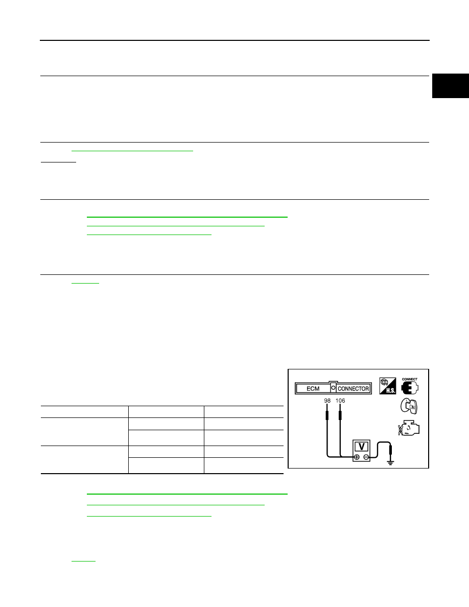
3.

Check voltage between ECM terminals 106 (APP sensor 1 sig-
nal), 98 (APP sensor 2 signal) and ground under the following
conditions.

4.

If NG, replace accelerator pedal assembly and go to next step.

5.

Perform 

EC-662, "Accelerator Pedal Released Position Learning"

.

6.

Perform 

EC-663, "Throttle Valve Closed Position Learning"

.

7.

Perform 

EC-663, "Idle Air Volume Learning"

.

Removal and Installation

INFOID:0000000001327007

ACCELERATOR PEDAL

Refer to 

ACC-3

.

Terminal

Accelerator pedal

Voltage

106
 (Accelerator pedal position 
sensor 1)

Fully released

0.5 - 1.0V

Fully depressed

3.9 - 4.7V

98
(Accelerator pedal position 
sensor 2)

Fully released

0.15 - 0.60V

Fully depressed

1.95 - 2.40V

MBIB0023E

EC-1110

< SERVICE INFORMATION >

[VK45DE]

DTC P2127, P2128 APP SENSOR

DTC P2127, P2128 APP SENSOR

Component Description

INFOID:0000000001327008

The accelerator pedal position sensor is installed on the upper end
of the accelerator pedal assembly. The sensor detects the accelera-
tor position and sends a signal to the ECM.
Accelerator pedal position sensor has two sensors. These sensors
are a kind of potentiometers which transform the accelerator pedal
position into output voltage, and emit the voltage signal to the ECM.
In addition, these sensors detect the opening and closing speed of
the accelerator pedal and feed the voltage signals to the ECM. The
ECM judges the current opening angle of the accelerator pedal from
these signals and controls the throttle control motor based on these
signals.
Idle position of the accelerator pedal is determined by the ECM
receiving the signal from the accelerator pedal position sensor. The ECM uses this signal for the engine oper-
ation such as fuel cut.

CONSULT-III Reference Value in Data Monitor Mode

INFOID:0000000001327009

Specification data are reference values.

*: Accelerator pedal position sensor 2 signal is converted by ECM internally. Thus, it differs from ECM terminal voltage.

On Board Diagnosis Logic

INFOID:0000000001327010

These self-diagnoses have the one trip detection logic.

FAIL-SAFE MODE

When the malfunction is detected, ECM enters fail-safe mode and the MIL lights up.

DTC Confirmation Procedure

INFOID:0000000001327011

NOTE:
If DTC Confirmation Procedure has been previously conducted, always turn ignition switch OFF and wait at
least 10 seconds before conducting the next test.

PBIB1741E

MONITOR ITEM

CONDITION

SPECIFICATION

ACCEL SEN 1

• Ignition switch: ON

(Engine stopped)

Accelerator pedal: Fully released

0.5 - 1.0V

Accelerator pedal: Fully depressed

4.0 - 4.8V

ACCEL SEN 2*

• Ignition switch: ON

(Engine stopped)

Accelerator pedal: Fully released

0.3 - 1.2V

Accelerator pedal: Fully depressed

3.9 - 4.8V

CLSD THL POS

• Ignition switch: ON

(Engine stopped)

Accelerator pedal: Fully released

ON

Accelerator pedal: Slightly depressed

OFF

DTC No.

Trouble diagnosis name

DTC detecting condition

Possible cause

P2127
2127

Accelerator pedal posi-
tion sensor 2 circuit low 
input

An excessively low voltage from the APP sen-
sor 2 is sent to ECM.

• Harness or connectors

(APP sensor 2 circuit is open or shorted.)
(TP sensor circuit is shorted.)

• Accelerator pedal position sensor

(APP sensor 2)

• Electric throttle control actuator

(TP sensor 1 and 2)

P2128
2128

Accelerator pedal posi-
tion sensor 2 circuit high 
input

An excessively high voltage from the APP sen-
sor 2 is sent to ECM.

Engine operating condition in fail-safe mode

The ECM controls the electric throttle control actuator in regulating the throttle opening in order for the idle position to be within +10 
degrees.
The ECM regulates the opening speed of the throttle valve to be slower than the normal condition.
So, the acceleration will be poor. 

DTC P2127, P2128 APP SENSOR

EC-1111

< SERVICE INFORMATION >

[VK45DE]

C

D

E

F

G

H

I

J

K

L

M

A

EC

N

P

O

TESTING CONDITION:
Before performing the following procedure, confirm that battery voltage is more than 8V at idle.
1.

Start engine and let it idle for 1 second.

2.

Check DTC.

3.

If DTC is detected, go to 

EC-1112, "Diagnosis Procedure"

.

Wiring Diagram

INFOID:0000000001327012

TBWM1355E

EC-1112

< SERVICE INFORMATION >

[VK45DE]

DTC P2127, P2128 APP SENSOR

Specification data are reference values and are measured between each terminal and ground.

CAUTION:

Do not use ECM ground terminals when measuring input/output voltage. Doing so may result in dam-
age to the ECM's transistor. Use a ground other than ECM terminals, such as the ground.

Diagnosis Procedure

INFOID:0000000001327013

1.

CHECK GROUND CONNECTIONS

1.

Turn ignition switch OFF.

2.

Loosen and retighten three ground screws on the body.
Refer to 

EC-723, "Ground Inspection"

.

OK or NG

OK

>> GO TO 2.

NG

>> Repair or replace ground connections.

2.

CHECK APP SENSOR 2 POWER SUPPLY CIRCUIT-I

TER-

MI-

NAL 

NO.

WIRE 

COLOR

ITEM

CONDITION

DATA (DC Voltage)

47

L

Sensor power supply (Throt-
tle position sensor)

[Ignition switch: ON]

Approximately 5V

82

B/W

Sensor ground
(APP sensor 1 / ICC steering 
switch / ASCD steering 
switch)

[Engine is running]
• Warm-up condition
• Idle speed

Approximately 0V

83

G/OR

Sensor ground
(APP sensor 2)

[Engine is running]
• Warm-up condition
• Idle speed

Approximately 0V

90

L/B

Sensor power supply
(APP sensor 1)

[Ignition switch: ON]

Approximately 5V

91

G

Sensor power supply
(APP sensor 2)

[Ignition switch: ON]

Approximately 5V

98

Y/R

Accelerator pedal position 
sensor 2

[Ignition switch: ON]
• Engine stopped
• Accelerator pedal: Fully released

0.15 - 0.60V

[Ignition switch: ON]
• Engine stopped
• Accelerator pedal: Fully depressed

1.95 - 2.40V

106

OR

Accelerator pedal position 
sensor 1

[Ignition switch: ON]
• Engine stopped
• Accelerator pedal: Fully released

0.5 - 1.0V

[Ignition switch: ON]
• Engine stopped
• Accelerator pedal: Fully depressed

3.9 - 4.7V

PBIB2195E


Content   ..  585  586  587  588   ..