Infiniti FX35 / FX45. Manual - part 529


  Index      Infiniti     Infiniti FX35 / FX45 (S50) - service repair manual 2008 year


Search            


Content   ..  527  528  529  530   ..


Infiniti FX35 / FX45. Manual - part 529


DTC P0172, P0175 FUEL INJECTION SYSTEM FUNCTION

EC-877

< SERVICE INFORMATION >

[VK45DE]

C

D

E

F

G

H

I

J

K

L

M

A

EC

N

P

O

Listen for an intake air leak after the mass air flow sensor.

OK or NG

OK

>> GO TO 3.

NG

>> Repair or replace.

3.

CHECK AIR FUEL RATIO (A/F) SENSOR 1 INPUT SIGNAL CIRCUIT

1.

Turn ignition switch OFF.

2.

Disconnect air fuel ratio (A/F) sensor 1 harness connector.

3.

Disconnect ECM harness connector.

4.

Check harness continuity between the following terminals.
Refer to Wiring Diagram.

5.

Check harness continuity between the following terminals and ground.
Refer to Wiring Diagram.

6.

Also check harness for short to power.

OK or NG

OK

>> GO TO 4.

NG

>> Repair open circuit or short to ground or short to power in harness or connectors.
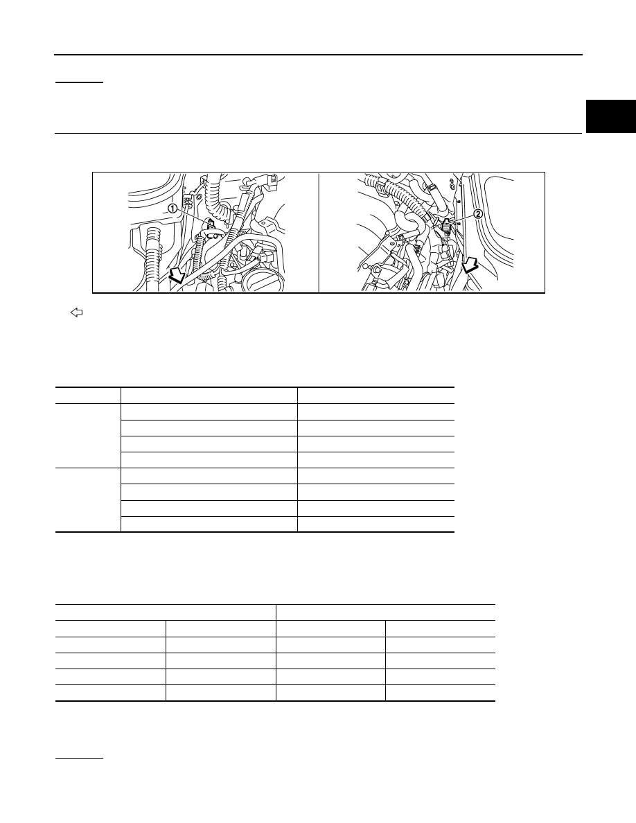
: Vehicle front

1.

A/F sensor 1 (Bank 2) 
harness connector

2.

A/F sensor 1 (Bank 1) 
harness connector

A/F sensor 1 terminal

ECM terminal

Bank 1

1

16

2

75

5

35

6

56

Bank 2

1

76

2

77

5

57

6

58

Continuity should exist.

Bank 1

Bank 2

A/F sensor 1 terminal

ECM terminal

A/F sensor 1 terminal

ECM terminal

1

16

1

76

2

75

2

77

5

35

5

57

6

56

6

58

Continuity should not exist.

PBIB3246E

EC-878

< SERVICE INFORMATION >

[VK45DE]

DTC P0172, P0175 FUEL INJECTION SYSTEM FUNCTION

4.

CHECK FUEL PRESSURE

1.

Release fuel pressure to zero. Refer to 

EC-665, "Fuel Pressure Check"

.

2.

Install fuel pressure gauge and check fuel pressure. Refer to 

EC-665, "Fuel Pressure Check"

.

OK or NG

OK

>> GO TO 6.

NG

>> GO TO 5.

5.

DETECT MALFUNCTIONING PART

Check the following.
• Fuel pump and circuit (Refer to 

EC-1155

.)

• Fuel pressure regulator (Refer to 

EC-665, "Fuel Pressure Check"

.)

>> Repair or replace.

6.

CHECK MASS AIR FLOW SENSOR

 With CONSULT-III

1.

Install all removed parts.

2.

Check “MASS AIR FLOW” in “DATA MONITOR” mode with CONSULT-III.

 With GST

1.

Install all removed parts.

2.

Check mass air flow sensor signal in “Service $01” with GST.

OK or NG

OK (With CONSULT-III)>>GO TO 7.
OK (Without CONSULT-III)>>GO TO 8.
NG

>> Check connectors for rusted terminals or loose connections in the mass air flow sensor circuit or

grounds. Refer to 

EC-768

.

7.

CHECK FUNCTION OF FUEL INJECTOR-I

 With CONSULT-III

1.

Start engine.

2.

Perform “POWER BALANCE” in “ACTIVE TEST” mode with CONSULT-III.

3.

Make sure that each circuit produces a momentary engine speed drop.

OK or NG

OK

>> GO TO 10.

NG

>> Perform trouble diagnosis for 

EC-1149

.

8.

CHECK FUNCTION OF FUEL INJECTOR-I

 Without CONSULT-III

1.

Turn ignition switch OFF.

2.

Disconnect harness connectors F21, F201 (Bank 1) and F41, F221 (Bank 2).

At idling: Approximately 350 kPa (3.57 kg/cm

2

, 51 psi)

2.0 - 6.0 g·m/sec:

at idling

7.0 - 20.0 g·m/sec:

at 2,500 rpm

2.0 - 6.0 g·m/sec:

at idling

7.0 - 20.0 g·m/sec:

at 2,500 rpm

DTC P0172, P0175 FUEL INJECTION SYSTEM FUNCTION

EC-879

< SERVICE INFORMATION >

[VK45DE]

C

D

E

F

G

H

I

J

K

L

M

A

EC

N

P

O

3.

Turn ignition switch ON.

4.

Check voltage between the following;
harness connector F21 terminal 5 and ground,
harness connector F41 terminal 5 and ground.

5.

Turn ignition switch OFF.

6.

Disconnect ECM harness connector.

7.

Check harness continuity between the following terminals.

8.

Also check harness for short to ground and short to power.

OK or NG

OK

>> GO TO 9.

NG

>> Perform trouble diagnosis for 

EC-1149

.

9.

CHECK FUNCTION OF FUEL INJECTOR-II

Provide battery voltage between the following terminals, and then
interrupt it. Listen to each fuel injector operating sound.

: Vehicle front

1.

Harness connectors F41, F221

2.

Harness connectors F21, F201

Voltage: Battery voltage

Cylinder

Harness connector terminal

ECM terminal

1

F21 terminal 3

23

3

F21 terminal 2

22

5

F21 terminal 1

21

7

F21 terminal 6

44

2

F41 terminal 3

42

4

F41 terminal 2

41

6

F41 terminal 1

40

8

F41 terminal 6

63

Continuity should exist.

PBIB3248E

PBIB0180E

Cylinder

Harness connector

terminal

(+)

(–)

1

F201

5

3

3

2

5

1

7

6

PBIB2449E

EC-880

< SERVICE INFORMATION >

[VK45DE]

DTC P0172, P0175 FUEL INJECTION SYSTEM FUNCTION

OK or NG

OK

>> GO TO 10.

NG

>> Perform trouble diagnosis for 

EC-1149

.

10.

CHECK FUEL INJECTOR

1.

Turn ignition switch OFF.

2.

Confirm that the engine is cooled down and there are no fire hazards near the vehicle.

3.

Remove fuel tube assembly. Refer to 

EM-190

.

Keep fuel hose and all fuel injectors connected to fuel tube.

4.

Disconnect all fuel injector harness connectors.

5.

Disconnect all ignition coil harness connectors.

6.

Prepare pans or saucers under each fuel injectors.

7.

Crank engine for about 3 seconds.
Make sure fuel does not drip from fuel injector.

OK or NG

OK (Does not drip.)>>GO TO 11.
NG (Drips.)>>Replace the fuel injectors from which fuel is dripping. Always replace O-ring with new one.

11.

CHECK INTERMITTENT INCIDENT

Refer to 

EC-717

.

>> INSPECTION END

2

F221

5

3

4

2

6

1

8

6

Operating sound should exist.

Cylinder

Harness connector

terminal

(+)

(–)


Content   ..  527  528  529  530   ..