Infiniti FX35 / FX45. Manual - part 498


  Index      Infiniti     Infiniti FX35 / FX45 (S50) - service repair manual 2008 year


Search            


Content   ..  496  497  498  499   ..


Infiniti FX35 / FX45. Manual - part 498


DTC P0037, P0038, P0057, P0058 HO2S2 HEATER

EC-753

< SERVICE INFORMATION >

[VK45DE]

C

D

E

F

G

H

I

J

K

L

M

A

EC

N

P

O

1.

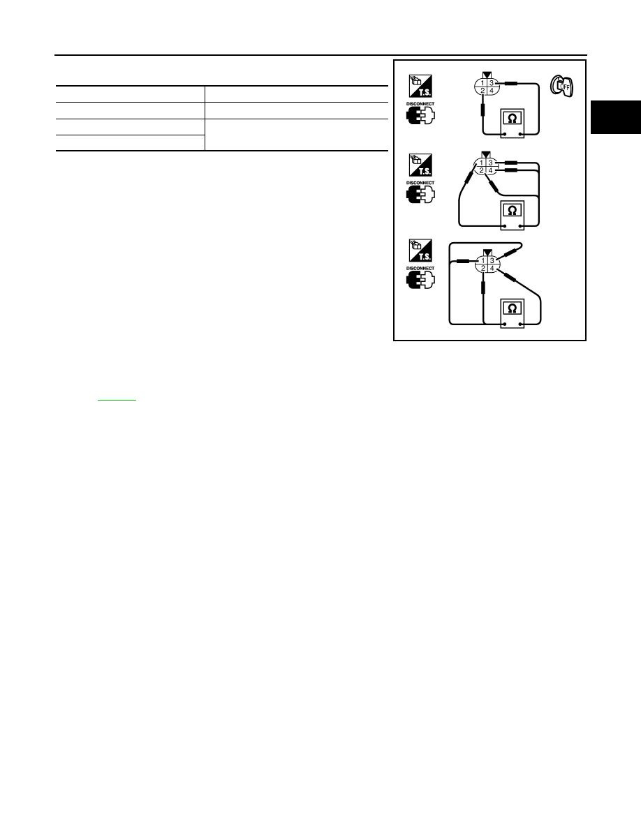
Check resistance between HO2S2 terminals as follows.

2.

If NG, replace heated oxygen sensor 2.

CAUTION:

• Discard any heated oxygen sensor which has been dropped

from a height of more than 0.5 m (19.7 in) onto a hard surface
such as a concrete floor; use a new one.

• Before installing new oxygen sensor, clean exhaust system

threads using Oxygen Sensor Thread Cleaner tool J-43897-18
or J-43897-12 and approved anti-seize lubricant.

Removal and Installation

INFOID:0000000001326577

HEATED OXYGEN SENSOR 2

Refer to 

EM-179

.

Terminal No.

Resistance

2 and 3

5.0 - 7.0 

 [at 25

°

C (77

°

F)]

1 and 2, 3, 4


(Continuity should not exist)

4 and 1, 2, 3

PBIB0970E

EC-754

< SERVICE INFORMATION >

[VK45DE]

DTC P0075, P0081 IVT CONTROL SOLENOID VALVE

DTC P0075, P0081 IVT CONTROL SOLENOID VALVE

Component Description

INFOID:0000000001326578

Intake valve timing control solenoid valve is activated by ON/OFF
pulse duty (ratio) signals from the ECM.
The intake valve timing control solenoid valve changes the oil
amount and direction of flow through intake valve timing control unit
or stops oil flow.
The longer pulse width advances valve angle.
The shorter pulse width retards valve angle.
When ON and OFF pulse widths become equal, the solenoid valve
stops oil pressure flow to fix the intake valve angle at the control
position.

CONSULT-III Reference Value in Data Monitor Mode

INFOID:0000000001326579

Specification data are reference values.

On Board Diagnosis Logic

INFOID:0000000001326580

DTC Confirmation Procedure

INFOID:0000000001326581

NOTE:
If DTC Confirmation Procedure has been previously conducted, always turn ignition switch OFF and
wait at least 10 seconds before conducting the next test.
1.

Start engine and let it idle for 5 seconds.

2.

Check 1st trip DTC.

3.

If 1st trip DTC is detected, go to 

EC-758, "Diagnosis Procedure"

.

PBIB1842E

MONITOR ITEM

CONDITION

SPECIFICATION

INT/V SOL (B1)
INT/V SOL (B2)

• Engine: After warming up
• Selector lever: P or N
• Air conditioner switch: OFF
• No  load

Idle

0% - 2%

2,000 rpm

Approx. 25% - 50%

DTC No.

Trouble diagnosis name

DTC detecting condition

Possible cause

P0075
0075
(Bank 1)

Intake valve timing control 
solenoid valve circuit

An improper voltage is sent to the ECM 
through intake valve timing control solenoid 
valve.

• Harness or connectors

(Intake valve timing control solenoid valve 
circuit is open or shorted.)

• Intake valve timing control solenoid valve

P0081
0081
(Bank 2)

DTC P0075, P0081 IVT CONTROL SOLENOID VALVE

EC-755

< SERVICE INFORMATION >

[VK45DE]

C

D

E

F

G

H

I

J

K

L

M

A

EC

N

P

O

Wiring Diagram

INFOID:0000000001326582

BANK 1

Specification data are reference values and are measured between each terminal and ground.
Pulse signal is measured by CONSULT-III.

CAUTION:

TBWM1342E

EC-756

< SERVICE INFORMATION >

[VK45DE]

DTC P0075, P0081 IVT CONTROL SOLENOID VALVE

Do not use ECM ground terminals when measuring input/output voltage. Doing so may result in dam-
age to the ECM's transistor. Use a ground other than ECM terminals, such as the ground.

: Average voltage for pulse signal (Actual pulse signal can be confirmed by oscilloscope.)

TER-

MI-

NAL 

NO.

WIRE 

COLOR

ITEM

CONDITION

DATA (DC Voltage)

10

OR

Intake valve timing control 
solenoid valve (Bank 1)

[Engine is running]
• Warm-up condition
• Idle speed

BATTERY VOLTAGE
(11 - 14V)

[Engine is running]
• Warm-up condition
• Engine speed: 2,000rpm

7 - 12V

111

W/B

ECM relay
(Self shut-off)

[Engine is running]
[Ignition switch: OFF]
• For a few seconds after turning ignition 

switch OFF

0 - 1.5V

[Ignition switch: OFF]
• More than a few seconds after turning igni-

tion switch OFF

BATTERY VOLTAGE
(11 - 14V)

119

120

R
R/B

Power supply for ECM

[Ignition switch: ON]

BATTERY VOLTAGE
(11 - 14V)

PBIB1790E


Content   ..  496  497  498  499   ..