Infiniti FX35 / FX45. Manual - part 432


  Index      Infiniti     Infiniti FX35 / FX45 (S50) - service repair manual 2008 year


Search            


Content   ..  430  431  432  433   ..


Infiniti FX35 / FX45. Manual - part 432


DTC P1805 BRAKE SWITCH

EC-489

< SERVICE INFORMATION >

[VQ35DE]

C

D

E

F

G

H

I

J

K

L

M

A

EC

N

P

O

1.

Turn ignition switch OFF.

2.

Disconnect ECM harness connector.

3.

Disconnect stop lamp switch harness connector.

4.

Check harness continuity between ECM terminal 101 and stop
lamp switch terminal 2.
Refer to Wiring Diagram.

5.

Also check harness for short to ground and short to power.

OK or NG

OK

>> GO TO 6.

NG

>> GO TO 5.

5.

DETECT MALFUNCTIONING PART

Check the following.
• Harness connectors E211, M41
• Harness for open or short between ECM and stop lamp switch

>> Repair open circuit or short to ground or short to power in harness or connectors.

6.

CHECK STOP LAMP SWITCH 

Refer to 

EC-489, "Component Inspection"

.

OK or NG

OK

>> GO TO 7.

NG

>> Replace stop lamp switch.

7.

CHECK INTERMITTENT INCIDENT

Refer to 

EC-139

.

>> INSPECTION END

Component Inspection

INFOID:0000000001326362
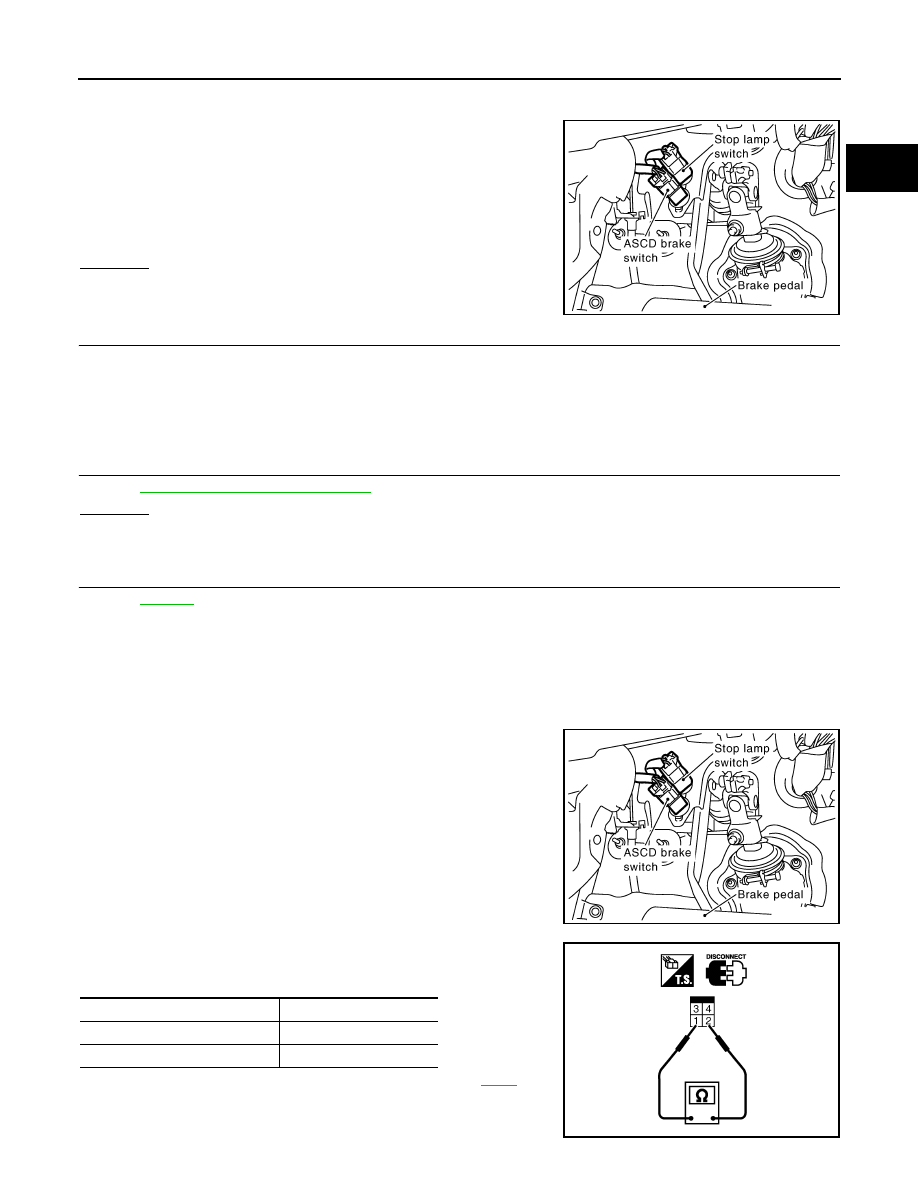
STOP LAMP SWITCH

1.

Disconnect stop lamp switch harness connector.

2.

Check continuity between stop lamp switch terminals 1 and 2
under the following conditions.

If NG, adjust stop lamp switch installation, refer to 

BR-5

, and

perform step 2 again.

Continuity should exist.

PBIB1605E

PBIB1605E

Conditions

Continuity

Brake pedal: Fully released

Should not exist

Brake pedal: Slightly depressed

Should exist

PBIB1185E

EC-490

< SERVICE INFORMATION >

[VQ35DE]

DTC P2100, P2103 THROTTLE CONTROL MOTOR RELAY

DTC P2100, P2103 THROTTLE CONTROL MOTOR RELAY

Component Description

INFOID:0000000001326363

Power supply for the throttle control motor is provided to the ECM via throttle control motor relay. The throttle
control motor relay is ON/OFF controlled by the ECM. When the ignition switch is turned ON, the ECM sends
an ON signal to throttle control motor relay and battery voltage is provided to the ECM. When the ignition
switch is turned OFF, the ECM sends an OFF signal to throttle control motor relay and battery voltage is not
provided to the ECM.

CONSULT-III Reference Value in Data Monitor Mode

INFOID:0000000001326364

Specification data are reference values.

On Board Diagnosis Logic

INFOID:0000000001326365

These self-diagnoses have the one trip detection logic.

FAIL-SAFE MODE

When the malfunction is detected, ECM enters fail-safe mode and the MlL lights up.

DTC Confirmation Procedure

INFOID:0000000001326366

NOTE:
If DTC Confirmation Procedure has been previously conducted, always turn ignition switch OFF and wait at
least 10 seconds before conducting the next test.

PROCEDURE FOR DTC P2100

1.

Turn ignition switch ON and wait at least 2 seconds.

2.

Start engine and let it idle for 5 seconds.

3.

Check DTC.

4.

If DTC is detected, go to 

EC-492, "Diagnosis Procedure"

.

 With GST

Follow the procedure “With CONSULT-III” above.

PROCEDURE FOR DTC P2103

TESTING CONDITION:
Before performing the following procedure, confirm that battery voltage is more than 8V.

1.

Turn ignition switch ON and wait at least 1 second.

2.

Check DTC.

3.

If DTC is detected, go to 

EC-492, "Diagnosis Procedure"

.

MONITOR ITEM

CONDITION

SPECIFICATION

THRTL RELAY

• Ignition switch: ON

ON

DTC No.

Trouble diagnosis name

DTC detecting condition

Possible cause

P2100
2100

Throttle control motor 
relay circuit open

ECM detects a voltage of power source for 
throttle control motor is excessively low.

• Harness or connectors

(Throttle control motor relay circuit is 
open)

• Throttle control motor relay

P2103
2103

Throttle control motor 
relay circuit short

ECM detects the throttle control motor relay is 
stuck ON.

• Harness or connectors

(Throttle control motor relay circuit is 
shorted)

• Throttle control motor relay

Engine operating condition in fail-safe mode

ECM stops the electric throttle control actuator control, throttle valve is maintained at a fixed opening (approx. 5 degrees) by the return 
spring.

DTC P2100, P2103 THROTTLE CONTROL MOTOR RELAY

EC-491

< SERVICE INFORMATION >

[VQ35DE]

C

D

E

F

G

H

I

J

K

L

M

A

EC

N

P

O

Wiring Diagram

INFOID:0000000001326367

Specification data are reference values and are measured between each terminal and ground.
Pulse signal is measured by CONSULT-III.

CAUTION:

TBWM1397E

EC-492

< SERVICE INFORMATION >

[VQ35DE]

DTC P2100, P2103 THROTTLE CONTROL MOTOR RELAY

Do not use ECM ground terminals when measuring input/output voltage. Doing so may result in dam-
age to the ECM's transistor. Use a ground other than ECM terminals, such as the ground.

: Average voltage for pulse signal (Actual pulse signal can be confirmed by oscilloscope.)

Diagnosis Procedure

INFOID:0000000001326368

1.

CHECK THROTTLE CONTROL MOTOR RELAY POWER SUPPLY CIRCUIT-I

1.

Turn ignition switch OFF.

2.

Check voltage between ECM terminal 104 and ground with
CONSULT-III or tester.

OK or NG

OK

>> GO TO 5.

NG

>> GO TO 2.

2.

CHECK THROTTLE CONTROL MOTOR RELAY POWER SUPPLY CIRCUIT-II

1.

Disconnect ECM harness connector.

2.

Disconnect IPDM E/R harness connector E9.

3.

Check continuity between ECM terminal 104 and IPDM E/R terminal 47.
Refer to Wiring Diagram.

4.

Also check harness for short to ground and short to power.

OK or NG

OK

>> GO TO 4.

NG

>> GO TO 3.

TER-

MI-

NAL 

NO.

WIRE 

COLOR

ITEM

CONDITION

DATA (DC Voltage)

3

R

Throttle control motor relay 
power supply

[Ignition switch: ON]

BATTERY VOLTAGE
(11 - 14V)

4

L/W

Throttle control motor 
(Close)

[Ignition switch: ON]
• Engine stopped
• Selector lever: D
• Accelerator pedal: Fully released

0 - 14V

5

L/B

Throttle control motor 
(Open)

[Ignition switch: ON]
• Engine stopped
• Selector lever: D
• Accelerator pedal: Fully depressed

0 - 14V

104

L/OR

Throttle control motor relay

[Ignition switch: OFF]

BATTERY VOLTAGE
(11 - 14V)

[Ignition switch: ON]

0 - 1.0V

PBIB1104E

PBIB1105E

Voltage: Battery voltage

PBIB1171E

Continuity should exist.


Content   ..  430  431  432  433   ..