Infiniti FX35 / FX45. Manual - part 424
DTC P1564 ICC STEERING SWITCH
EC-457
< SERVICE INFORMATION >
[VQ35DE]
C
D
E
F
G
H
I
J
K
L
M
A
EC
N
P
O
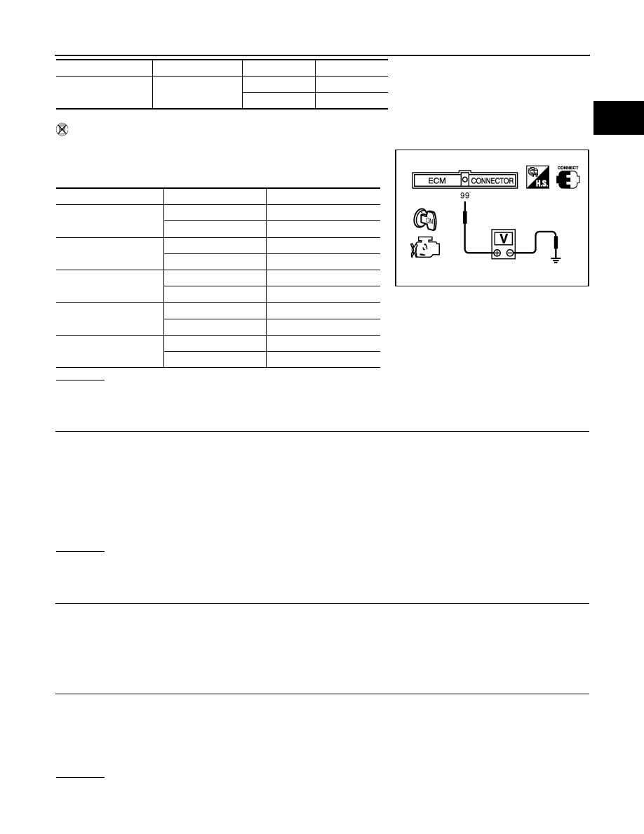
Without CONSULT-III
1.
Turn ignition switch ON.
2.
Check voltage between ECM terminal 99 and ground with press-
ing each button.
OK or NG
OK
>> GO TO 8.
NG
>> GO TO 3.
3.
CHECK ICC STEERING SWITCH GROUND CIRCUIT FOR OPEN AND SHORT
1.
Turn ignition switch OFF.
2.
Disconnect combination switch harness connector.
3.
Disconnect ECM harness connector.
4.
Check harness continuity between combination switch terminal 15 and ECM terminal 82.
Refer to Wiring Diagram.
5.
Also check harness for short to ground and short to power.
OK or NG
OK
>> GO TO 5.
NG
>> GO TO 4.
4.
DETECT MALFUNCTIONING PART
Check the following.
• Combination switch (spiral cable)
• Harness for open and short between ECM and combination switch
>> Repair open circuit or short to ground or short to power in harness or connectors.
5.
CHECK ICC STEERING SWITCH INPUT SIGNAL CIRCUIT FOR OPEN AND SHORT
1.
Check harness continuity between ECM terminal 99 and combination switch terminal 14.
Refer to Wiring Diagram.
2.
Also check harness for short to ground and short to power.
OK or NG
OK
>> GO TO 7.
DISTANCE switch
DIST SW
Pressed
ON
Released
OFF
Switch
Monitor item
Condition
Indication
Switch
Condition
Voltage [V]
MAIN switch
Pressed
Approx. 0
Released
Approx. 4.3
CANCEL switch
Pressed
Approx. 1.3
Released
Approx. 4.3
RESUME/ACCELER-
ATE switch
Pressed
Approx. 3.7
Released
Approx. 4.3
SET/COAST switch
Pressed
Approx. 3.0
Released
Approx. 4.3
DISTANCE switch
Pressed
Approx. 2.2
Released
Approx. 4.3
PBIB0311E
Continuity should exist.
Continuity should exist.