Infiniti FX35 / FX45. Manual - part 423


  Index      Infiniti     Infiniti FX35 / FX45 (S50) - service repair manual 2008 year


Search            


Content   ..  421  422  423  424   ..


Infiniti FX35 / FX45. Manual - part 423


DTC P1564 ICC STEERING SWITCH

EC-453

< SERVICE INFORMATION >

[VQ35DE]

C

D

E

F

G

H

I

J

K

L

M

A

EC

N

P

O

DTC P1564 ICC STEERING SWITCH

Component Description

INFOID:0000000001326313

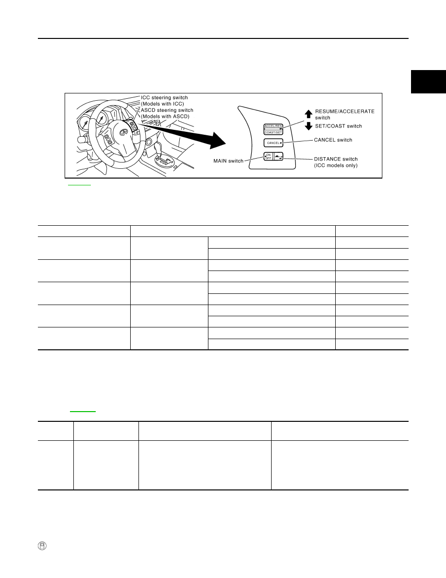
ICC steering switch has variant values of electrical resistance for each button. ECM reads voltage variation of
switch, and determines which button is operated.

Refer to 

ACS-7

 for the ICC function.

CONSULT-III Reference Value in Data Monitor Mode

INFOID:0000000001326314

Specification data are reference values.

On Board Diagnosis Logic

INFOID:0000000001326315

• This self-diagnosis has the one trip detection logic.
• The MIL will not light up for this self-diagnosis.
NOTE:
If DTC P1564 is displayed with DTC P0605, first perform the trouble diagnosis for DTC P0605.
Refer to 

EC-422

.

DTC Confirmation Procedure

INFOID:0000000001326316

NOTE:
If DTC Confirmation Procedure has been previously conducted, always turn ignition switch OFF and wait at
least 10 seconds before conducting the next test. 

 WITH CONSULT-III

PBIB3255E

MONITOR ITEM

CONDITION

SPECIFICATION

MAIN SW

• Ignition switch: ON

MAIN switch: Pressed

ON

MAIN switch: Released

OFF

CANCEL SW

• Ignition switch: ON

CANCEL switch: Pressed

ON

CANCEL switch: Released

OFF

RESUME/ACC SW

• Ignition switch: ON

RESUME/ACCELERATE switch: Pressed

ON

RESUME/ACCELERATE switch: Released

OFF

SET SW

• Ignition switch: ON

 SET/COAST switch: Pressed

ON

SET/COAST switch: Released

OFF

DIST SW

• Ignition switch: ON

DISTANCE switch: Depressed

ON

DISTANCE switch: Released

OFF

DTC No.

Trouble Diagnosis 

Name

DTC Detecting Condition

Possible Cause

P1564
1564

ICC steering switch

• An excessively high voltage signal from the 

ICC steering switch is sent to ECM.

• ECM detects that input signal from the ICC 

steering switch is out of the specified range.

• ECM detects that the ICC steering switch is 

stuck ON.

• Harness or connectors

(ICC steering switch circuit is open or shorted.)

• ICC steering switch
• ECM

EC-454

< SERVICE INFORMATION >

[VQ35DE]

DTC P1564 ICC STEERING SWITCH

1.

Turn ignition switch ON and wait at least 10 seconds.

2.

Press MAIN switch for at least 10 seconds, then release it and wait at least 10 seconds.

3.

Press RESUME/ACCELERATE switch for at least 10 seconds, then release it and wait at least 10 sec-
onds.

4.

Press SET/COAST switch for at least 10 seconds, then release it and wait at least 10 seconds.

5.

Press DISTANCE switch for at least 10 seconds, then release it and wait at least 10 seconds.

6.

Press CANCEL switch for at least 10 seconds, then release it and wait at least 10 seconds.

7.

Check DTC.

8.

If DTC is detected, go to 

EC-456, "Diagnosis Procedure"

.

DTC P1564 ICC STEERING SWITCH

EC-455

< SERVICE INFORMATION >

[VQ35DE]

C

D

E

F

G

H

I

J

K

L

M

A

EC

N

P

O

Wiring Diagram

INFOID:0000000001326317

Specification data are reference values and are measured between each terminal and ground.

CAUTION:

Do not use ECM ground terminals when measuring input/output voltage. Doing so may result in dam-
age to the ECM's transistor. Use a ground other than ECM terminals, such as the ground.

TBWM0732E

EC-456

< SERVICE INFORMATION >

[VQ35DE]

DTC P1564 ICC STEERING SWITCH

Diagnosis Procedure

INFOID:0000000001326318

1.

CHECK GROUND CONNECTIONS

1.

Turn ignition switch OFF.

2.

Loosen and retighten ground screw on the body. Refer to 

EC-144, "Ground Inspection"

.

OK or NG

OK

>> GO TO 2.

NG

>> Repair or replace ground connections.

2.

CHECK ICC STEERING SWITCH CIRCUIT

 With CONSULT-III

1.

Turn ignition switch ON.

2.

Select “MAIN SW”, “RESUME/ACC SW”, “SET SW”, “DIST SW” and “CANCEL SW” in “DATA MONITOR”
mode with CONSULT-III.

3.

Check each item indication under the following conditions.

TERMI-

NAL 

NO.

WIRE 

COLOR

ITEM

CONDITION

DATA (DC Voltage)

82

B/W

Sensor ground
(ICC steering switch)

[Engine is running]
• Warm-up condition
• Idle speed

Approximately 0V

99

G/Y

ICC steering switch

[Ignition switch: ON]
• ICC steering switch: OFF

Approximately 4.3V

[Ignition switch: ON]
• MAIN switch: Pressed

Approximately 0V

[Ignition switch: ON]
• CANCEL switch: Pressed

Approximately 1.3V

[Ignition switch: ON]
• RESUME/ACCELERATE switch: Pressed

Approximately 3.7V

[Ignition switch: ON]
• SET/COAST switch: Pressed

Approximately 3.0V

[Ignition switch: ON]
• DISTANCE switch: Pressed

Approximately 2.2V

PBIB2625E

Switch

Monitor item

Condition

Indication

MAIN switch

MAIN SW

Pressed

ON

Released

OFF

CANCEL switch

CANCEL SW

Pressed

ON

Released

OFF

RESUME/ACCELER-
ATE switch

RESUME/ACC SW

Pressed

ON

Released

OFF

SET/COAST switch

SET SW

Pressed

ON

Released

OFF


Content   ..  421  422  423  424   ..