Infiniti FX35 / FX45. Manual - part 401


  Index      Infiniti     Infiniti FX35 / FX45 (S50) - service repair manual 2008 year


Search            


Content   ..  399  400  401  402   ..


Infiniti FX35 / FX45. Manual - part 401


DTC P0447 EVAP CANISTER VENT CONTROL VALVE

EC-365

< SERVICE INFORMATION >

[VQ35DE]

C

D

E

F

G

H

I

J

K

L

M

A

EC

N

P

O

2.

Check portion B of EVAP canister vent control valve for being
rusted.
If NG, replace EVAP canister vent control valve.
If OK, go to next step.

3.

Reconnect harness connectors disconnected.

4.

Turn ignition switch ON.

5.

Perform “VENT CONTROL/V” in “ACTIVE TEST” mode.

6.

Check air passage continuity and operation delay time.
Make sure new O-ring is installed properly.

Operation takes less than 1 second.

If NG, replace EVAP canister vent control valve.
If OK, go to next step.

7.

Clean the air passage (portion A to B) of EVAP canister vent control valve using an air blower.

8.

Perform step 6 again.
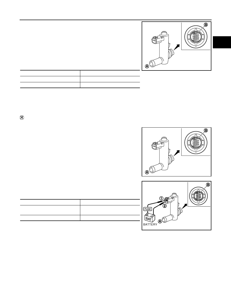
 Without CONSULT-III

1.

Remove EVAP canister vent control valve from EVAP canister.

2.

Check portion B of EVAP canister vent control valve for being
rusted.

3.

Check air passage continuity and operation delay time under the
following conditions.
Make sure new O-ring is installed properly.

Operation takes less than 1 second.

If NG, replace EVAP canister vent control valve.
If OK, go to next step.

4.

Clean the air passage (portion A to B) of EVAP canister vent control valve using an air blower.

5.

Perform step 3 again.

Condition VENT CONTROL/V

Air passage continuity between A and B

ON

No

OFF

Yes

PBIB1033E

PBIB1033E

Condition

Air passage continuity between A and B

12V direct current supply between
 terminals 1 and 2

No

OFF

Yes

PBIB1034E

EC-366

< SERVICE INFORMATION >

[VQ35DE]

DTC P0448 EVAP CANISTER VENT CONTROL VALVE

DTC P0448 EVAP CANISTER VENT CONTROL VALVE

Component Description

INFOID:0000000001326192

The EVAP canister vent control valve is located on the EVAP canis-
ter and is used to seal the canister vent.
This solenoid valve responds to signals from the ECM. When the
ECM sends an ON signal, the coil in the solenoid valve is energized.
A plunger will then move to seal the canister vent. The ability to seal
the vent is necessary for the on board diagnosis of other evaporative
emission control system components.
This solenoid valve is used only for diagnosis, and usually remains
opened.
When the vent is closed, under normal purge conditions, the evapo-
rative emission control system is depressurized and allows EVAP
Control System diagnosis.

CONSULT-III Reference Value in Data Monitor Mode

INFOID:0000000001326193

Specification data are reference values.

On Board Diagnosis Logic

INFOID:0000000001326194

DTC Confirmation Procedure

INFOID:0000000001326195

NOTE:
If DTC Confirmation Procedure has been previously conducted, always turn ignition switch OFF and wait at
least 10 seconds before conducting the next test.

1.

Turn ignition switch ON and wait at least 5 seconds.

2.

Turn ignition switch OFF and wait at least 10 seconds.

3.

Start engine and let it idle for at least 1 minute. 

4.

Repeat next procedures three times.

a.

Increase the engine speed up to 3,000 to 3,500 rpm and keep it for 2 minutes and 50 seconds to 3 min-
utes.
Never exceed 3 minutes.

b.

Fully released accelerator pedal and keep engine idle for about 5 seconds.

PBIB1263E

PBIB1611E

MONITOR ITEM

CONDITION

SPECIFICATION

VENT CONT/V

• Ignition switch: ON

OFF

DTC No.

Trouble diagnosis name

DTC detecting condition

Possible cause

P0448
0448

EVAP canister vent con-
trol valve close

EVAP canister vent control valve remains 
closed under specified driving conditions.

• EVAP canister vent control valve
• EVAP control system pressure sensor 

and the circuit

• Blocked rubber tube to EVAP canister 

vent control valve

• EVAP canister is saturated with water

DTC P0448 EVAP CANISTER VENT CONTROL VALVE

EC-367

< SERVICE INFORMATION >

[VQ35DE]

C

D

E

F

G

H

I

J

K

L

M

A

EC

N

P

O

5.

Check 1st trip DTC.

6.

If 1st trip DTC is detected, go to 

EC-369, "Diagnosis Procedure"

.

If 1st trip DTC is not detected, go to the next step.

7.

Repeat next procedure 20 times.

a.

Quickly increase the engine speed up to 4,000 to 4,500 rpm or more and keep it for 25 to 30 seconds.

b.

Fully released accelerator pedal and keep engine idle for at least 35 seconds.

8.

Check 1st trip DTC.

9.

If 1st trip DTC is detected, go to 

EC-369, "Diagnosis Procedure"

.

PBIB0972E

EC-368

< SERVICE INFORMATION >

[VQ35DE]

DTC P0448 EVAP CANISTER VENT CONTROL VALVE

Wiring Diagram

INFOID:0000000001326196

Specification data are reference values and are measured between each terminal and ground.

CAUTION:

Do not use ECM ground terminals when measuring input/output voltage. Doing so may result in dam-
age to the ECM's transistor. Use a ground other than ECM terminals, such as the ground.

TBWM1391E


Content   ..  399  400  401  402   ..