Infiniti FX35 / FX45. Manual - part 384
DTC P0181 FTT SENSOR
EC-297
< SERVICE INFORMATION >
[VQ35DE]
C
D
E
F
G
H
I
J
K
L
M
A
EC
N
P
O
5.
CHECK FUEL TANK TEMPERATURE SENSOR GROUND CIRCUIT FOR OPEN AND SHORT
1.
Turn ignition switch OFF.
2.
Disconnect “unified meter and A/C amp.” harness connector.
3.
Check harness continuity between “fuel level sensor unit and fuel pump” terminal 5 and “unified meter and
A/C amp.” terminal 36. Refer to Wiring Diagram.
4.
Also check harness for short to ground and short to power.
OK or NG
OK
>> GO TO 7.
NG
>> GO TO 6.
6.
DETECT MALFUNCTIONING PART
Check the following.
• Harness connectors B1, M11
• Harness for open or short between “fuel level sensor unit and fuel pump” and “unified meter and A/C amp.”
>> Repair open circuit or short to ground or short to power in harness or connector.
7.
CHECK FUEL TANK TEMPERATURE SENSOR
EC-297, "Component Inspection"
OK or NG
OK
>> GO TO 8.
NG
>> Replace fuel level sensor unit.
8.
CHECK INTERMITTENT INCIDENT
>> INSPECTION END
Component Inspection
INFOID:0000000001326114
FUEL TANK TEMPERATURE SENSOR
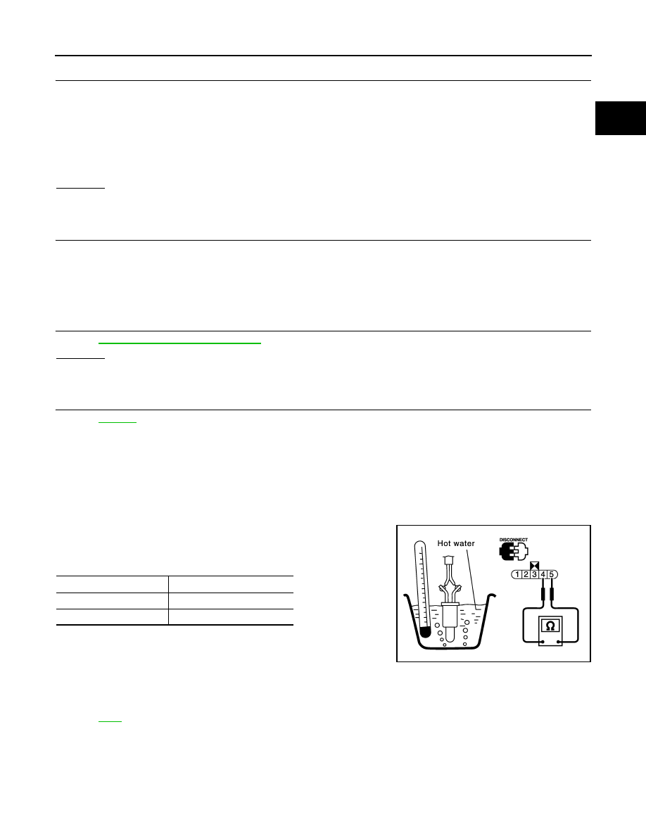
1.
Remove fuel level sensor unit.
2.
Check resistance between “fuel level sensor unit and fuel pump”
terminals 4 and 5 by heating with hot water as shown in the fig-
ure.
If NG, replace fuel level sensor unit.
Removal and Installation
INFOID:0000000001326115
FUEL TANK TEMPERATURE SENSOR
Continuity should exist.
Temperature
°
C (
°
F)
Resistance k
Ω
20 (68)
2.3 - 2.7
50 (122)
0.79 - 0.90
PBIB0931E