Infiniti FX35 / FX45. Manual - part 352
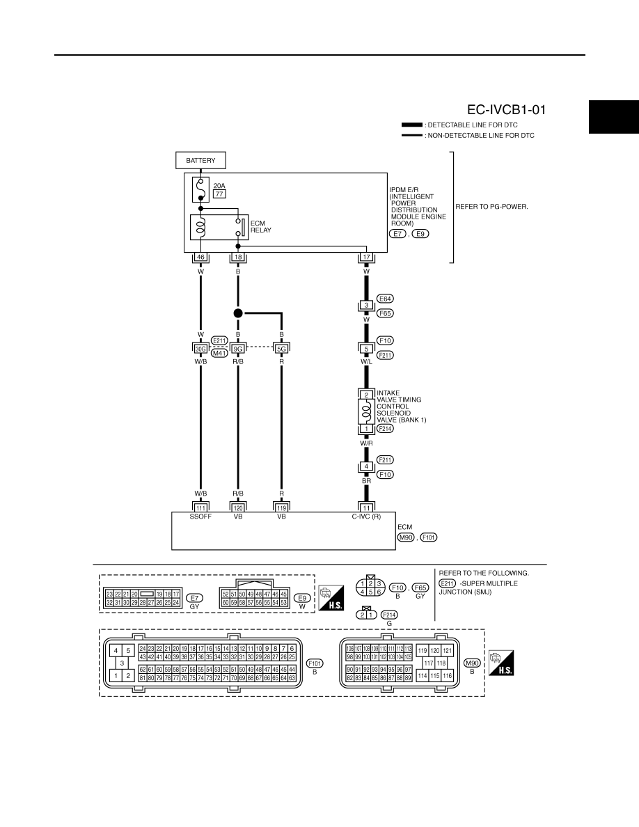
DTC P0075, P0081 IVT CONTROL SOLENOID VALVE
EC-169
< SERVICE INFORMATION >
[VQ35DE]
C
D
E
F
G
H
I
J
K
L
M
A
EC
N
P
O
Wiring Diagram
INFOID:0000000001325985
BANK 1
Specification data are reference values and are measured between each terminal and ground.
Pulse signal is measured by CONSULT-III.
CAUTION:
TBWM1394E