Infiniti FX35 / FX45. Manual - part 273
CO-22
< SERVICE INFORMATION >
[VQ35DE]
WATER PUMP
WATER PUMP
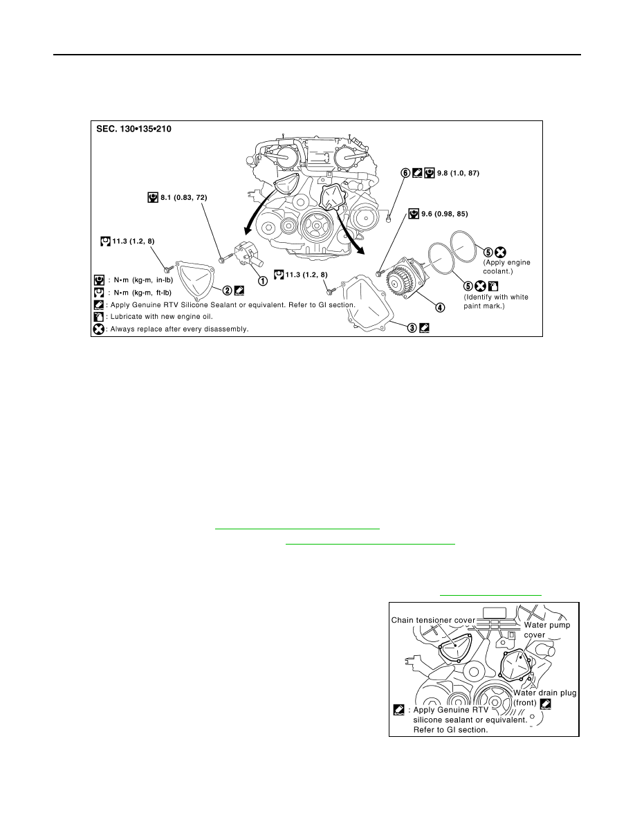
Component
INFOID:0000000001325856
Removal and Installation
INFOID:0000000001325857
CAUTION:
• When removing water pump assembly, be careful not to get engine coolant on drive belts.
• Water pump cannot be disassembled and should be replaced as a unit.
• After installing water pump, connect hose and clamp securely, then check for leaks using the radia-
tor cap tester (commercial service tool) and the radiator cap tester adapter (commercial service
tool).
REMOVAL
1.
Remove front engine undercover with power tool.
2.
Remove drive belts. Refer to
EM-15, "Removal and Installation"
3.
Drain engine coolant from radiator. Refer to
CO-10, "Changing Engine Coolant"
.
CAUTION:
• Perform this step when the engine is cold.
• Do not spill engine coolant on drive belts.
4.
Remove air duct (inlet), power duct and air cleaner case assembly. Refer to
5.
Remove water drain plug (front) on water pump side of cylinder
block to drain engine coolant from engine inside.
6.
Remove chain tensioner cover and water pump cover from front timing chain case.
• Use the seal cutter [SST: KV10111100 (J37228)] to cut liquid gasket for removal.
7.
Remove timing chain tensioner (primary) as follows:
1.
Timing chain tensioner (primary)
2.
Chain tensioner cover
3.
Water pump cover
4.
Water pump
5.
O-rings
6.
Water drain plug (front)
SBIA0482E
PBIC2662E