Infiniti FX35 / FX45. Manual - part 201


  Index      Infiniti     Infiniti FX35 / FX45 (S50) - service repair manual 2008 year


Search            


Content   ..  199  200  201  202   ..


Infiniti FX35 / FX45. Manual - part 201


REMOTE KEYLESS ENTRY SYSTEM

BL-71

< SERVICE INFORMATION >

C

D

E

F

G

H

J

K

L

M

A

B

BL

N

O

P

5.

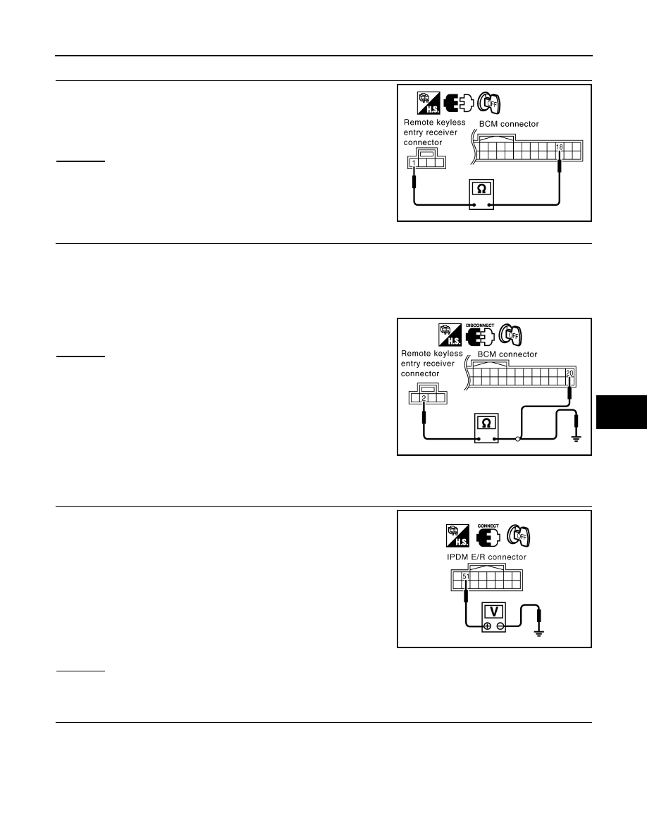
CHECK REMOTE KEYLESS ENTRY RECEIVER GROUND CIRCUIT

1.

Check continuity between remote keyless entry receiver con-
nector M78 terminal 1 (B) and BCM connector M1 terminal 18
(B)

OK or NG

OK

>>

Check harness connection.

• If it is OK, replace BCM.
• If it is NG, repair or replace malfunction part.

NG

>> Repair or replace the harness.

6.

CHECK REMOTE KEYLESS ENTRY RECEIVER SIGNAL CIRCUIT

1.

Check continuity between remote keyless entry receiver connector M78 terminal 2 (Y) and BCM connec-
tor M1 terminal 20 (Y).

2.

Check continuity between remote keyless entry receiver connector M78 terminal 2 (Y) and ground.

OK or NG

OK

>>

Check harness connection.

• If it is OK, replace remote keyless entry receiver.
• If it is NG, repair or replace malfunction part.

NG

>> Repair or replace harness.

Check IPDM E/R Operation

INFOID:0000000001327828

1.

CHECK IPDM E/R INPUT VOLTAGE

Check voltage between IPDM E/R connector E9 terminal 51 and
ground.

OK or NG

OK

>> Replace IPDM E/R.

NG

>> GO TO 2.

2.

CHECK IPDM E/R HARNESS

1.

Turn ignition switch OFF.

2.

Disconnect IPDM E/R and horn relay connector.

1 (B) – 18 (B)

: Continuity should exist.

PIIB3952E

2 (Y) – 20 (Y)

: Continuity should exist.

2 (Y) – Ground

: Continuity should not exist.

PIIA9633E

51 (SB) – Ground

: Battery voltage

PIIA6403E

BL-72

< SERVICE INFORMATION >

REMOTE KEYLESS ENTRY SYSTEM

3.

Check continuity between IPDM E/R connector E9 terminal 51
and horn relay connector E10 terminal 1.

OK or NG

OK

>> Check harness connection.

NG

>> Repair or replace harness.

Check Hazard Warning Lamp Function

INFOID:0000000001327829

1.

CHECK HAZARD WARNING LAMP

Do hazard warning lamp flash with hazard switch?

YES or NO

YES

>> Hazard warning lamp circuit is OK.

NO

>> Check hazard circuit. Refer to 

LT-78

.

Check Horn Function

INFOID:0000000001327830

First perform the “SELF-DIAG RESULTS” in “BCM” with CONSULT-III, then perform the trouble diagnosis of
malfunction system indicated “SELF-DIAG RESULTS” of “BCM”. Refer to 

BCS-13, "U1000 CAN Communica-

tion Circuit"

.

1.

CHECK HORN FUNCTION

Does horn sound with horn switch?

YES or NO

YES

>> Horn circuit is OK.

NO

>> Check horn circuit. Refer to 

WW-48, "Wiring Diagram - HORN -"

.

Check Headlamp Function

INFOID:0000000001327831

First perform the “SELF-DIAG RESULTS” in “BCM” with CONSULT-III, then perform the trouble diagnosis of
malfunction system indicated “SELF-DIAG RESULTS” of “BCM”. Refer to 

BCS-13, "U1000 CAN Communica-

tion Circuit"

.

1.

CHECK HEADLAMP FUNCTION

Does headlamp come on when turning lighting switch “ON”?
YES or NO

YES

>> Headlamp operation circuit is OK.

NO

>> Check headlamp system. Refer to 

LT-5, "System Description"

.

Check Map Lamp and Ignition Keyhole Illumination Function

INFOID:0000000001327832

1.

CHECK MAP LAMP AND IGNITION KEYHOLE ILLUMINATION FUNCTION

When map lamp switch is in “DOOR” position, open the front door (LH or RH).

OK or NG

51 (SB) – 1 (SB)

: Continuity should exist.

PIIA6404E

 Map lamp and ignition keyhole illumination should illuminate.

REMOTE KEYLESS ENTRY SYSTEM

BL-73

< SERVICE INFORMATION >

C

D

E

F

G

H

J

K

L

M

A

B

BL

N

O

P

OK

>> Replace BCM.

NG

>> Check ignition illumination circuit. Refer to 

LT-138

.

ID Code Entry Procedure

INFOID:0000000001327833

KEY FOB ID SET UP WITH CONSULT-III

NOTE:
• If a key fob is lost, the ID code of the lost key fob must be erased to prevent unauthorized use. A spe-

cific ID code can be erased with CONSULT-III. However, when the ID code of a lost key fob is not
known, all controller ID codes should be erased. After all ID codes are erased, the ID codes of all
remaining and/or new key fobs must be re-registered.

1.

Touch “WORK SUPPORT”.

2.

The items are shown on the figure can be set up.
• “REMO CONT ID REGIST”

Use this mode to register a key fob ID code.
NOTE:
Register the ID code when key fob or BCM is replaced, or when additional key fob is required.

• “REMO CONT ID ERASUR”

Use this mode to erase a key fob ID code.

• “REMO CONT ID CONFIR”

Use this mode to confirm if a key fob ID code is registered or not.

BL-74

< SERVICE INFORMATION >

REMOTE KEYLESS ENTRY SYSTEM

KEY FOB ID SET UP WITHOUT CONSULT-III

NOTE:
• If a key fob is lost, the ID code of the lost key fob must be erased to prevent unauthorized use. A specific ID

code can be erased with CONSULT-III. However, when the ID code of a lost key fob is not known, all control-
ler ID codes should be erased. After all ID codes are erased, the ID codes of all remaining and/or new key
fobs must be re-registered.
To erase all ID codes in memory, register one ID code (key fob) five times. After all ID codes are erased, the
ID codes of all remaining and/or new key fobs must be re-registered.

PIIA2839E


Content   ..  199  200  201  202   ..