Infiniti FX35 / FX45. Manual - part 194
POWER DOOR LOCK SYSTEM
BL-43
< SERVICE INFORMATION >
C
D
E
F
G
H
J
K
L
M
A
B
BL
N
O
P
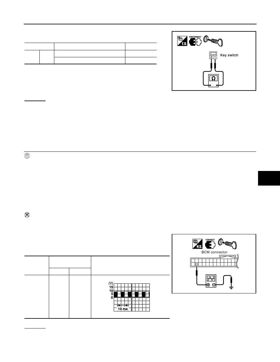
1.
Disconnect key switch connector.
2.
Check continuity between key switch terminals 1 and 2.
OK or NG
OK
>>
Check the following.
• 15A fuse (No. 22, located in fuse and fusible link block)
• Harness for open or short between key switch and fuse
• Harness for open or short between BCM and key switch
NG
>> Replace key switch or key switch and ignition knob switch.
Check Door Lock and Unlock Switch
INFOID:0000000001327805
1.
CHECK DOOR LOCK AND UNLOCK SWITCH INPUT SIGNAL
With CONSULT-III
Check door lock and unlock switch (“CDL LOCK SW” and “CDL UNLOCK SW”) in DATA MONITOR mode with
CONSULT-III.
• When door lock and unlock switch is turned to LOCK:
• When door lock and unlock switch is turned to UNLOCK:
Without CONSULT-III
1.
Remove key from ignition key cylinder.
2.
Check the signal between BCM connector M3 terminal 22 and ground with oscilloscope when door lock
and unlock switch is turned “LOCK” or “UNLOCK”.
3.
Make sure signals which are shown in the figure below can be
detected during 10 second just after door lock and unlock switch
is turned “LOCK” or “UNLOCK”.
OK or NG
OK
>> Door lock and unlock switch circuit is OK.
NG
>> GO TO 2.
Terminal
Condition of key switch
Continuity
1
2
Key is inserted in IGN key cylinder.
Yes
Key is removed from IGN key cylinder.
No
PIIA2627E
CDL LOCK SW
: ON
CDL UNLOCK SW
: ON
Connector
Terminal
(Wire color)
Signal
(Reference value)
(+)
(–)
M3
22 (OR)
Ground
PIIA6379E
PIIA1297E