Infiniti FX35 / FX45. Manual - part 169


  Index      Infiniti     Infiniti FX35 / FX45 (S50) - service repair manual 2008 year


Search            


Content   ..  167  168  169  170   ..


Infiniti FX35 / FX45. Manual - part 169


AV-130

< SERVICE INFORMATION >

NAVIGATION SYSTEM

5.

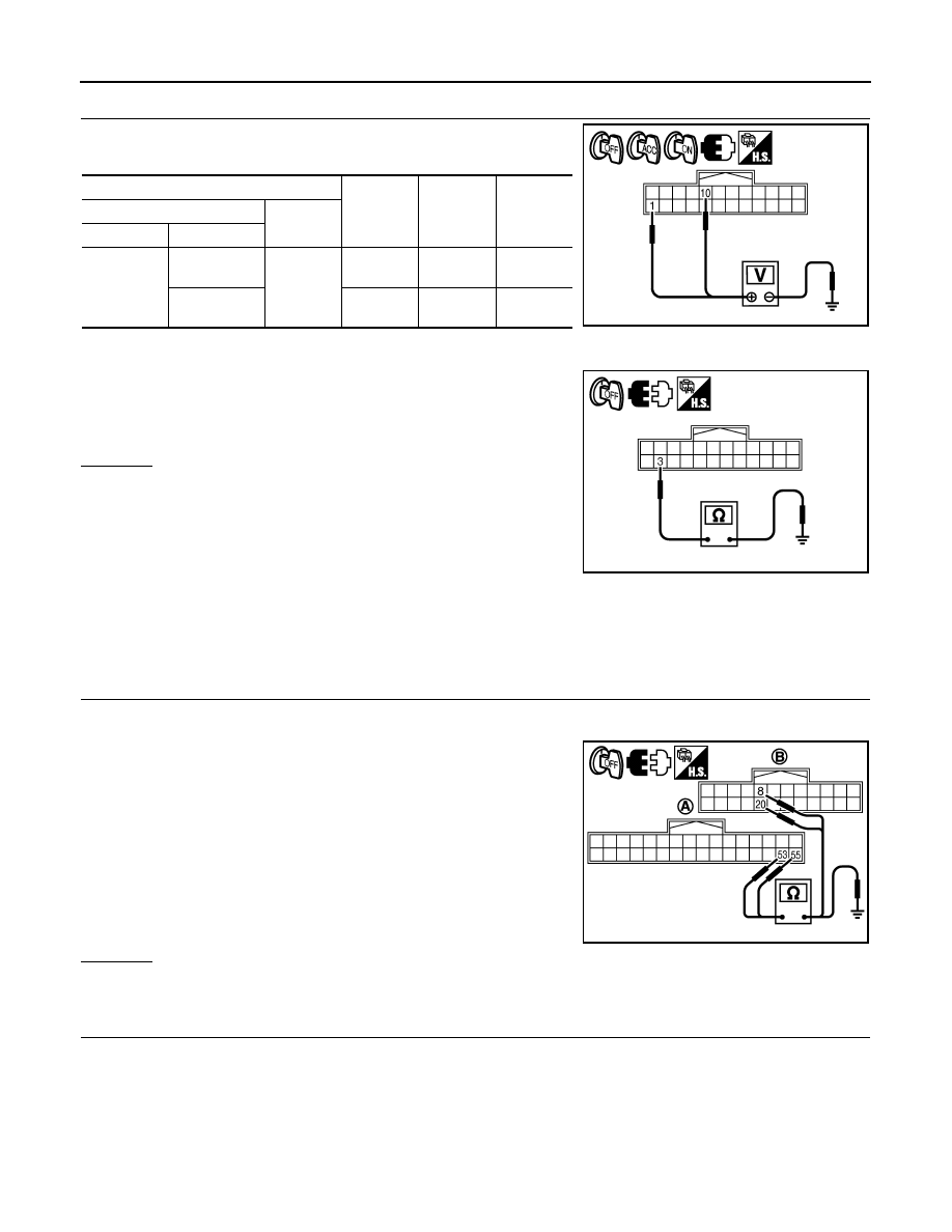
CHECK DISPLAY CONTROL UNIT POWER SUPPLY AND GROUND CIRCUIT

1.

Check voltage between display control unit harness connector
terminals and ground.

2.

Turn ignition switch OFF.

3.

Disconnect display control unit connector.

4.

Check continuity between display control unit harness connector
M75 terminal 3 and ground.

OK or NG

OK

>> Replace display control unit.

NG

>> Repair harness or connector.

Status Screen for Audio and A/C Is Not Displayed When Showing Map Screen

INFOID:0000000001328761

Symptom: Status screen is not displayed in the lower portion of map screen when operating audio system and
A/C system.

1.

CHECK HARNESS

1.

Turn ignition switch OFF.

2.

Disconnect display control unit and display connectors.

3.

Check continuity between display control unit harness connector
(A) M76 terminals 53, 55 and display harness connector (B)
M63 terminals 20, 8.

4.

Check continuity between display control unit harness connector
(A) M76 terminals 53, 55 and ground.

OK or NG

OK

>> GO TO 2.

NG

>> Repair harness or connector.

2.

CHECK VERTICAL SYNCHRONIZING (VP) SIGNAL

1.

Connect display control unit and display connectors.

2.

Turn ignition switch ON.

Terminals

OFF

ACC

ON

(+)

(–)

Connector

Terminal

M75

1

Ground

Battery 
voltage

Battery 
voltage

Battery 
voltage

10

0 V

Battery 
voltage

Battery 
voltage

3 – Ground

: Continuity should exist.

SKIB7843E

SKIB7844E

53 – 20

: Continuity should exist.

55 – 8

: Continuity should exist.

53, 55 – Ground

: Continuity should not exist.

SKIB7850E

NAVIGATION SYSTEM

AV-131

< SERVICE INFORMATION >

C

D

E

F

G

H

I

J

L

M

A

B

AV

N

O

P

3.

Check voltage waveform between display control unit harness
connector M76 terminal 53 and ground with CONSULT-III or
oscilloscope.

OK or NG

OK

>> GO TO 3.

NG

>> Replace display.

3.

CHECK HORIZONTAL SYNCHRONIZING (HP) SIGNAL

Check voltage waveform between display control unit harness con-
nector M76 terminal 55 and ground with CONSULT-III or oscillo-
scope.

OK or NG

OK

>> Replace display control unit.

NG

>> Replace display.

Vehicle Mark Is Not Displayed Properly

INFOID:0000000001328762

Symptom: Vehicle mark is not displayed at the vehicle driving position properly.

1.

NAVIGATION SYSTEM ADJUSTMENT

1.

Select “Navigation” in Confirmation/Adjustment mode, and adjust items, “Steering Angle Adjustment” and
“Speed Calibration”. Refer to 

AV-119, "Confirmation/Adjustment Mode"

.

2.

Check symptom with driving.

Is any malfunction observed?

YES

>> GO TO 2.

NO

>> INSPECTION END

2.

SELF-DIAGNOSIS OF NAVI

Start self-diagnosis of NAVI, and check any malfunction related to GPS. Refer to 

AV-117, "Self-Diagnosis

Mode (NAVI)"

.

Is any malfunction related to GPS observed?

YES

>> Repair malfunctioning part.

NO

>> GO TO 3.

3.

CHECK VEHICLE SIGNAL

Select “Vehicle Signals” in Confirmation/Adjustment mode, and check the vehicle speed signal and reverse
signal inputting to NAVI control unit. Refer to 

AV-119, "Confirmation/Adjustment Mode"

.

OK or NG

OK

>> Limit of position detection capacity.

NG

>> • Check NAVI control unit vehicle speed signal circuit, and repair malfunctioning part.

53 – Ground:

SKIB7851E

SKIB3598E

55 – Ground:

SKIB7852E

SKIB3601E

AV-132

< SERVICE INFORMATION >

NAVIGATION SYSTEM

• Check NAVI control unit reverse signal circuit, and repair malfunctioning part.

Tint Is Strange for the RGB Image

INFOID:0000000001328763

Symptom: Tint of all RGB images is strange.

1.

CHECK HARNESS

1.

Turn ignition switch OFF.

2.

Disconnect display control unit and display connectors.

3.

Check the malfunctioning circuit according to the symptoms.

• Light blue (Cyan) tinged screen

Check continuity between display control unit harness connector
(A) M76 terminal 50 and display harness connector (B) M63 termi-
nal 17.

Check continuity between display control unit harness connector
(A) M76 terminal 50 and ground.

• Purple (Magenta) tinged screen

Check continuity between display control unit harness connector
(A) M76 terminal 52 and display harness connector (B) M63 termi-
nal 6.

Check continuity between display control unit harness connector
(A) M76 terminal 52 and ground.

• Yellow tinged screen

Check continuity between display control unit harness connector
(A) M76 terminal 54 and display harness connector (B) M63 termi-
nal 18.

Check continuity between display control unit harness connector
(A) M76 terminal 54 and ground.

OK or NG

OK

>> GO TO 2.

NG

>> Repair harness or connector.

2.

CHECK RGB SIGNAL

1.

Connect display control unit and display connectors.

2.

Turn ignition switch ON.

3.

Start Confirmation/Adjustment mode. Refer to 

AV-119, "Confirmation/Adjustment Mode"

.

4.

Display color bar by selecting “Display Color Spectrum Bar” on Display Diagnosis screen. Refer to 

AV-

119, "Confirmation/Adjustment Mode"

.

5.

Check the malfunctioning circuit according to the symptoms.

50 – 17

: Continuity should exist.

50 – Ground

: Continuity should not exist.

SKIB7853E

52 – 6

: Continuity should exist.

52 – Ground

: Continuity should not exist.

SKIB7854E

54 – 18

: Continuity should exist.

54 – Ground

: Continuity should not exist.

SKIB7855E

NAVIGATION SYSTEM

AV-133

< SERVICE INFORMATION >

C

D

E

F

G

H

I

J

L

M

A

B

AV

N

O

P

• Light blue (Cyan) tinged screen

Check voltage waveform between display control unit harness con-
nector M76 terminal 50 and ground with CONSULT-III or oscillo-
scope.

• Purple (Magenta) tinged screen

Check voltage waveform between display control unit harness con-
nector M76 terminal 52 and ground with CONSULT-III or oscillo-
scope.

• Yellow tinged screen

Check voltage waveform between display control unit harness con-
nector M76 terminal 54 and ground with CONSULT-III or oscillo-
scope.

OK or NG

OK

>> Replace display.

NG

>> Replace display control unit.

Tint Is Strange for the RGB Image (Only NAVI Screen)

INFOID:0000000001328764

Symptom: Tint of map screen is strange. (Status screen for audio and A/C, TRIP screen and FUEL ECON-
OMY screen are normal.)

1.

CHECK HARNESS

1.

Turn ignition switch OFF.

2.

Disconnect NAVI control unit and display unit connectors.

3.

Check the malfunctioning circuit according to the symptoms.

• Light blue (Cyan) tinged screen

50 – Ground:

SKIB7856E

SKIB7769E

52 – Ground:

SKIB7857E

SKIB7770E

54 – Ground:

SKIB7858E

SKIB7771E


Content   ..  167  168  169  170   ..