Infiniti FX35 / FX45. Manual - part 159
AV-90
< SERVICE INFORMATION >
NAVIGATION SYSTEM
• The gyro (angular speed sensor) and the DVD-ROM drive are
built-in units that control the navigation functions.
• Signals are received from the gyro, the vehicle speed sensor, and
the GPS antenna. Vehicle location is determined by combining this
data with the data contained in the DVD-ROM map. Locational
information is shown on liquid crystal display panel.
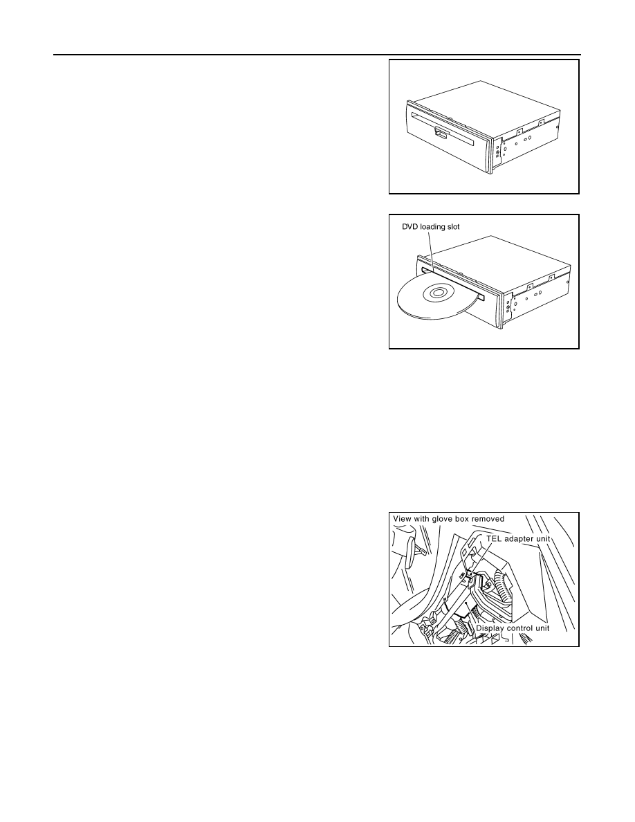
DVD-ROM Drive
Maps, traffic control regulations, and other pertinent information can
be easily read from the DVD-ROM.
DVD-ROM
• The DVD-ROM has maps, traffic control regulations, and other pertinent information.
• To improve DVD-ROM map matching and route determination functions, the DVD-ROM uses an exclusive
Nissan format. Therefore, the use of a DVD-ROM provided by other manufacturers cannot be used.
Gyro (Angular Speed Sensor)
• The oscillator gyro sensor is used to detect changes in vehicle steering angle.
• The gyro is built into the navigation (NAVI) control unit.
GPS ANTENNA
The GPS antenna receives and amplifies the radio waves from the GPS satellites, and then transmits the GPS
signal to NAVI control unit.
DISPLAY CONTROL UNIT
• Display control unit draws a status of the audio and air conditioner,
a TRIP screen, a FUEL ECONOMY screen, etc., and transmits the
image signals to the display screen.
• It receives operation signals of audio and air conditioner from A/C
and AV switch, and transmits the operation signal of audio to the
audio unit via the communication line and transmits the operation
signal of air conditioner to the meter and A/C amp. via CAN com-
munication.
DISPLAY
SKIB3892E
SKIB6982E
SKIB8638E