Index Infiniti Infiniti FX35 / FX45 (S50) - service repair manual 2008 year
Search
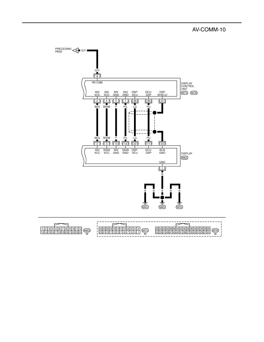
Content .. 151 152 153 154 ..
Infiniti FX35 / FX45. Manual - part 153
AV-66
< SERVICE INFORMATION >
INTEGRATED DISPLAY SYSTEM
TKWM4429E